Certifying duplex LC to LC multimode links - CertiFiber Pro
This article describes the correct method for certifying duplex LC to LC multimode links using the CertiFiber Pro. This method meets the Encircled Flux launch requirements of ANSI/TIA-526-14-C and IEC 61280-4-1:2010. As with all fiber testing, inspection is a critical component to successful certification. Without inspection, you may end up damaging the installed connectors. The CertiFiber Pro has a USB camera option for the inspection of end face connectors. Users are encouraged to take advantage of this. Additionally, the CertiFiber Pro with the USB camera option can automatically grade a fiber end face to IEC 61300-3-35 Ed 2, in around one second. Various tips are available including APC and MTP.
Before proceeding to test, ensure you have the correct test limit configured for your CertiFiber Pro. We cannot tell you which test limit to select as cabling vendors offering warranties often have stricter requirements than those found in ANSI/TIA and ISO/IEC standards. In this example, we shall use ANSI/TIA-568.3-E as our test limit. If you are using ISO/IEC limits or vendor specific limits, the test methodology described here is the same. Failing to use a 1 jumper reference for the testing of installed links could result in the rejection of your warranty application. It could also lead to negative loss or optimistic results.
Test reference cords (TRCs)
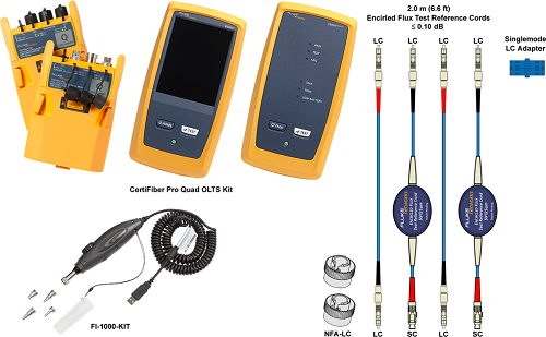
If the TRCs are bad, your test results will be bad too. It represents the largest volume of calls for support. The procedure found here includes a method to verify your TRCs before and during testing. The Fluke Networks TRCs are specially tuned for your CertiFiber Pro multimode source, ensuring Encircled Flux (EF) compliance at the end of the test cord in accordance with ANSI/TIA-526-14-C and IEC 61280-4-1:2010. EF compliance cannot be guaranteed using non-Fluke Networks EF-TRCs. If EF compliance is not a requirement, you may decide to use your own TRCs. If you choose to do this, you must use a mandrel and you must use non bend insensitive multimode fiber (BIMMF). Using BIMMF with a mandrel results in the higher order modes being stripped out at 1300 nm only. Simply put, your 850 nm loss results will be pessimistic. Sourcing non BIMMF is getting to be a challenge. Buyer beware.
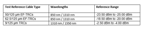
- MRC-50EFC-SCLCKIT-M : Multimode Encircled Flux compliant test reference cord kit (2 m) for testing 50 µm LC terminated fibers (2 SC/LC, 2 LC/LC)
- MRC-62EFC-SCLCKITM : Multimode Encircled Flux compliant test reference cord kit (2 m) for testing 62.5 µm LC terminated fibers (2 SC/LC, 2 LC/LC)
Setting up your CertiFiber Pro
1. Tap PROJECT > CHANGE PROJECT > NEW PROJECT.
2. Enter a name for your project "KB Article Example" followed by DONE. (It can be renamed later if necessary)
3. With the fiber module inserted you will see the following screen:
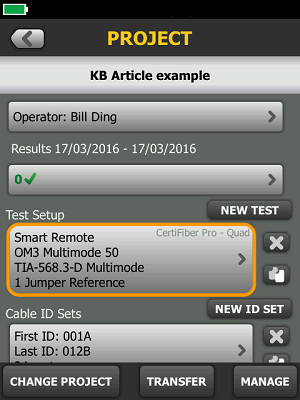
If not, tap the area under Test Setup > Module and change to CertiFiber Pro.
4. Tap Smart Remote above to see the following options:
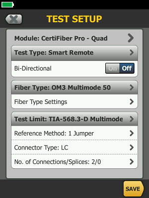
- Test Type: This governs the type of test. Since we are testing a duplex link, leave it as Smart Remote.
- Bi-Directional: The standards and most cabling vendors do not require this for Tier 1 testing - check your test specification.
- Fiber Type: This changes the refractive index setting which is used to determine the length of the fiber under test.
- Test Limit: It is critical to get in writing the test limit you are to use. There may be a custom test limit requirement for your installation.
- Reference Method: This must be set to 1 Jumper when link testing for warranty applications. Changing this can affect your loss budget (test limit).
- Connector Type: Set to LC, noting this has no impact on the outcome of the test results.
- No. of Connections/Splices: This directly affects the loss budget (test limit) used for standards such as TIA and ISO where the loss budget is based on the number of connections, splices and length of fiber. Unlike DTX, simply enter the number of connections and splices present in a single strand of fiber. CertiFiber Pro will take care of the math for you based on your Reference Method setting.
참조 설정
The leading cause of negative loss/optimistic looking results is the use of the 2 jumper reference. That's where the reference is set using 2 jumpers and a bulkhead adapter - shown below. You may have been doing this for the past 20 years, but this reference method is incorrect for the testing of installed links.
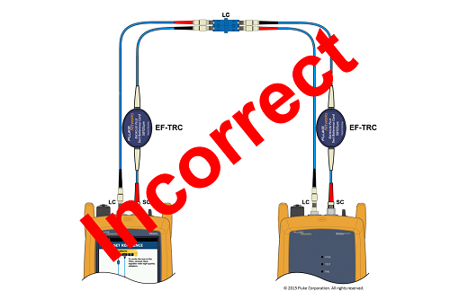
Follow these instructions and your negative losses will be a thing of the past.
1. Power on the main and remote sources. Allow them to stabilize. If the instruments have been sitting in the location of your test area, 5 minutes is usually long enough. If there is a significant temperature change from where they were stored to where you are using them, you will need to allow them to stabilize for much longer. We shall check the sources for stability during this procedure.
2. From the HOME screen, tap SET REF > RUN WIZARD > NEXT.
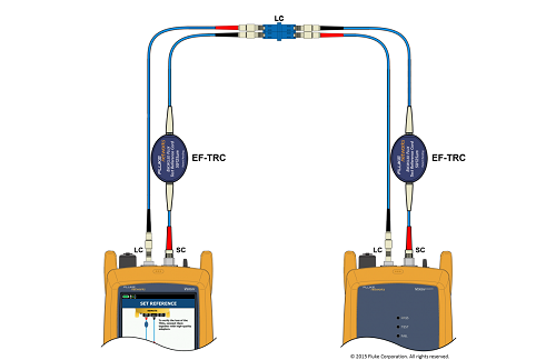
3. Connect the main and remote units together:
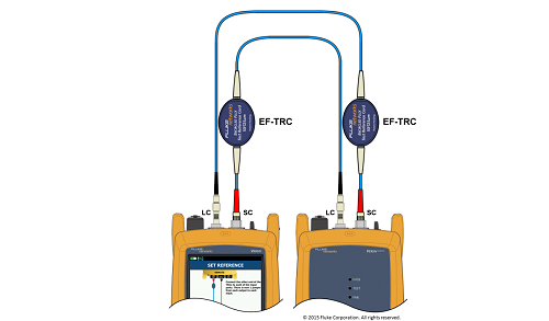
4. Tap SET REFERENCE.
(If you get Warning: Check fiber connections. The measured power levels are outside the range expected...... Tap OK > View Reference. Look to the fiber with the lower reference power, where -27 dBm is worse than -25 dBm. Inspect and clean the TRC. You may need to clean the OUTPUT port on your module too. Once done, press HOME and start the procedure again.)
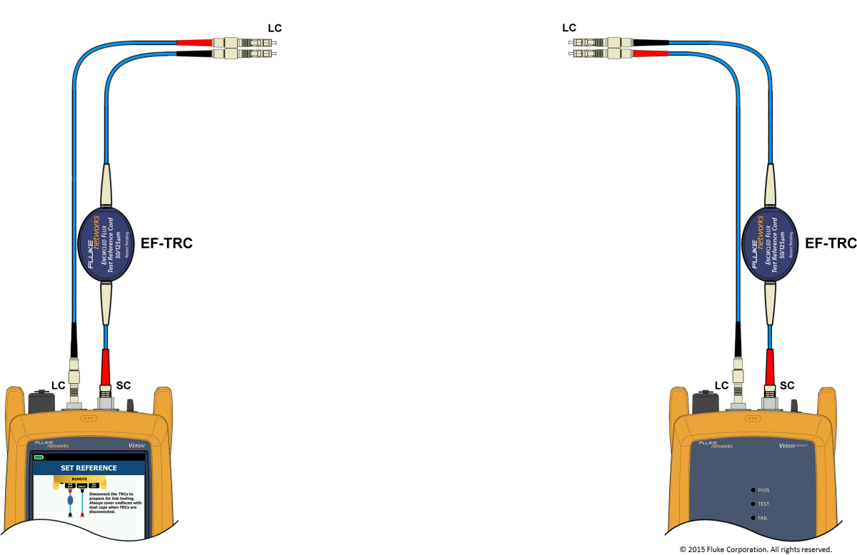
5. Tap NEXT and disconnect the TRCs from the INPUT ports (never disconnect from the OUTPUT ports)
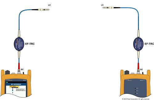
6. Tap NEXT and insert your known good LC to LC TRCs into the INPUT ports:
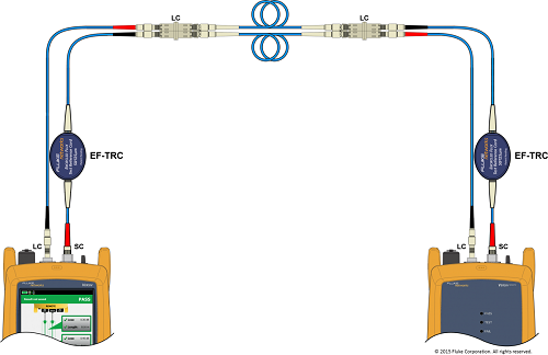
7. Tap NEXT, then join the main and remote together using singlemode rated bulkhead adapters. (Singlemode rated bulkhead adapters typically provide better alignment)
8. Tap NEXT > TRC Verification to verify the TRCs performance.
9. The goal for multimode is better than 0.15 dB. Losses greater than 0.15 dB will adversely affect the losses reported when you test your installed link.
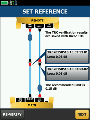
The results of the TRC verification are automatically stored in the Versiv mainframe. The Cable ID used to store the TRC verification is based on the date and time the verification was carried out. In the example above, we know it was done 2015년 5월 18일 at 1:53 pm. If you wanted to ensure your sources have stabilized, you could tap RE-VERIFY to see if the outcome changed. If it changes by more than ± 0.02 dB, your sources have not stabilized.
10. Tap NEXT and disconnect the units from the bulkhead adapters.
11. Press the HOME key - you are now ready to test.
12. Connect to your link.
13. Press TEST and in 3 seconds you will have certified both fibers at 850 nm and 1300 nm.
Note: Consider adding a requirement to verify your TRCs every 500 tests. Include the results of the TRC verification with your certification results.


