ST to ST duplex fiber loss testing using the DSP-FTA Series
The following article describes how to test an ST to ST duplex fiber link using a modified TIA/EIA Method B for multimode and TIA/EIA Method A.1 for singlemode. Since the DSP-FTA Series fiber apdaters have SC input ports, it is not possible to use the 1 jumper TIA/EIA Method B for multimode and TIA/EIA Method A.1 for singlemode.
ANSI/TIA-568-C.0 permits an alternative to Method B, so long as that method is documented:
To make this measurement, you will need three sets of hybrid PRECISION TEST REFERENCE CORDS, cleaning supplies and a fiber end face inspection device.
Before you start, clean AND INSPECT all end faces of your test reference cords using a fiberscope. Failure to do so will result in erratic readings. You should inspect and clean the test reference cords every 24 to 48 tests and reset the reference if needed. 왜 그렇습니까? You can pick up debris from the connectors you are testing. You can easily become a victim of cross contamination where you damage the connectors you are testing and your test reference cords.
You should verify your cords are of "test reference quality".
학습 내용:
- Fiber Testing
ANSI/TIA-568-C.0 permits an alternative to Method B, so long as that method is documented:
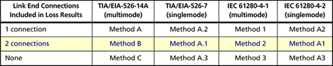
NOTE – TIA-526-14-A and TIA-526-7 contain a discussion of three reference methods. The one jumper reference methods (Method B and Method A.1, respectively) provide test results inclusive of the connections made at the test jumpers to the cabling link and all connections and splices that may be within the cabling link. Certain fiber optic connector types, including array connectors, cannot be tested using Method B or Method A.1. In such cases, the two or three jumper methods may be required. Such testing is permitted but the test method should be documented with the measurement results.
To make this measurement, you will need three sets of hybrid PRECISION TEST REFERENCE CORDS, cleaning supplies and a fiber end face inspection device.
For a list of available accessories,
Before you start, clean AND INSPECT all end faces of your test reference cords using a fiberscope. Failure to do so will result in erratic readings. You should inspect and clean the test reference cords every 24 to 48 tests and reset the reference if needed. 왜 그렇습니까? You can pick up debris from the connectors you are testing. You can easily become a victim of cross contamination where you damage the connectors you are testing and your test reference cords.
You should verify your cords are of "test reference quality".
- Power on the Main Unit and Smart Remote. Allow them to stabilize for at least 5 minutes before proceeding.
- On your DSP-4x00 CabeAnalyzer, rotate the dial to SETUP.
- Press the ENTER key and select your TEST STANDARD and CABLE TYPE.

- Press the F4 key and go to Page 6 of 7.
Change the ADAPTER TYPE to ST and the NUMBER OF ADAPTERS to 2. (Assuming you are testing panel to panel)
The ADAPTER TYPE will not affect the outcome of your test result, it is used for documentation purposes only.
The NUMBER OF ADAPTERS WILL AFFECT THE OUTCOME OF YOUR TEST RESULT. It is always the number of adapters ADDED per fiber path after you set the reference.
- Rotate the dial to SPECIAL FUNCTIONS, highlight Set Fiber Reference and press the ENTER key.
- Connect the SC to ST reference cords together: (Never remove the SC plug from the Output Port)
- Press the TEST key:
- You should see something similar to this:

If you are using 62.5/125 µm with the DSP-FTA410/420, you should expect a value better than -20.50 dBm.
If you are using 50/125 µm with the DTSP-FTA410/420, you should expect a value better than -24.50 dBm.
If you are using the DSP-FTA430 or DSP-FTA440, you should expect to see a value better than -9.00 dBm.
참고: -24.00 dBm is better than -24.50 dBm
Values within these ranges do not guarantee your test reference cords are clean. You must continually inspect and clean your test reference cords to avoid negative loss readings.
- Rotate the dial to AUTOTEST.
- Disconnect the SC to ST test reference cords:
- Add in the short ST to ST test reference cord:
The short test reference cord adds back in one mated connection that was referenced out earlier, making the adapter count 2 and consistent with Method B and Method A.1. You need to make sure it is configured A-A and B-B to maintain the correct polarity.
- Connect to the fiber to be tested:
- Press the TEST key.
학습 내용:
- Fiber Testing


