ISO/IEC 14763-3 testing ST to ST (Duplex Singlemode) DTX-SFM
Last date of manufacture: March 31st, 2006
Replacement product: DTX-SFM2
If you are applying for a cabling warranty, please check with your vendor in advance to see if this method is still acceptable.
ISO/IEC 11801 now refers fibre testing to ISO/IEC 14763-3. More importantly, the limits have changed and we'll show you how in this article.
This standard permits two methods:
- 3 Jumper: If the test equipment does not have changeable adapters on the input ports (DTX-MFM)
- 1 Jumper: If the test equipment does have changeable adapters on the input ports (DTX-SFM2)
Since you have the DTX-MFMs shown below, we'll show you the 3 Jumper method described in this article.
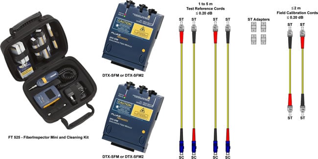
Items required in addition to a DTX CableAnalyzer:
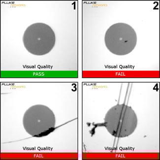
클리닝은 필수입니다. It is the single most reason for ending up with negative loss values. You cannot clean without some means of visually inspecting the end face. This can be anything from a simple Fiber Viewer to a Video Scope such as the FiberInspector Mini shown above. If you have no inspection device, you cannot proceed. Let's define what is acceptable and not acceptable.
 |
|
The Test Reference Cords (TRCs) are critical to a successful measurement. Your singlemode TRCs loss MUST not exceed 0.20 dB at each end. And yes, you must inspect and clean these TRCs every time you use them - even new ones out of the bag.
Where did Fluke Networks get that 0.20 dB requirement?
ISO/IEC 14763-3 requires that the TRC must not exceed 0.10 dB for multimode and 0.20 dB for singlemode at the connectors.
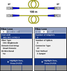
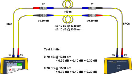
In this example, we're going to test a 100 m duplex 9/125 µm singlemode fibre link with ST connectors at each end to ISO/IEC 14763-3.
Setting up the DTX CableAnalyzer
-
With the fibre modules inserted into the DTX CableAnalyzer, power up the main and remote units.
Sources will need at least five minutes to stabilize, longer in colder or hotter environments.
-
Rotate the dial on the DTX CableAnalyzer to SETUP.
-
Select Fiber Loss and press ENTER.
-
Change the Test Limit to ISO/IEC 14763-3.
-
Change the Fiber Type to the cable you are testing.
This setting changes the Refractive Index (n) value. The DTX uses n to calculate the length of the fibre. You can manually enter the n values in Tab 3 of the Setup. If you cannot find your cable in the DTX Cable Library, look to the cable vendor's website for their datasheet. Since the ISO/IEC 14763-3 limit is calculated based on length, it is important to get this value right.
-
The Number of Adapters is going to be 0.
This is always the number of adapters per fibre strand added after the reference has been set.
-
Set the Connector Type to ST.
This will not affect the outcome of the result. It only affects the help screens and is of course recorded with the test result.
-
Set the Test Method to 3 Jumper. (With this Test Limit, it will affect the outcome of the result)
-
Clean AND inspect the TRCs.
-
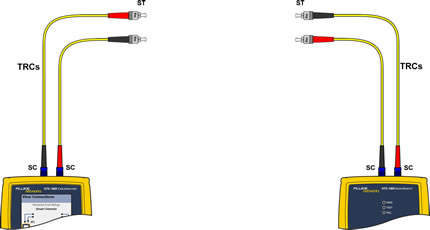
Connect the main and remote units together as shown below.
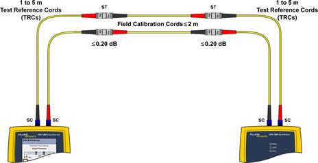
Mandrels must NOT be used.
-
Rotate the dial to SPECIAL FUNCTIONS.
-
With Set Reference selected, press ENTER then TEST.
-
You will then be presented with the results of the Reference.
For 9/125 µm it should be better than -8.00 dBm where -7.50 dBm is better than -8.00 dBm.
These values reflect the cleanliness of the Ports and TRCs. The fact that your reference values are better than the minimum stated above does not mean they are good/clean.
-
Press F2 OK.
-
You can enter the length of your TRCs here. It does not affect the outcome of the test, but will be displayed on the test report.

-
Press F2 OK when done.
-
Remove the Field Calibration Cord and put the dust caps back on the ends.
Never disconnect from the Output Ports. Doing so invalidates the reference you just set.
-
Connect the TRCs to the link you're testing.
-
Rotate the dial to AUTOTEST and press TEST.
The 0.30 dB at the connectors is not an error.
ISO/IEC 14763-3 states that the maximum permitted loss between a singlemode TRC and a random (installed) fibre connector is 0.50 dB. But don't forget, we referenced out 0.20 dB in step 10. So the actual allowable loss is 0.50 dB - 0.20 dB = 0.30 dB
There has been some dispute over this calculation. An addendum to ISO/IEC 14763-3 gives the formulaee in an easier way to understand and clarifies the issue. The 0.6 dB below consists of two 0.30 dB TRCs to random fibre connectors. Your DTX is correct.
Using the default three test cord reference method specified in 9.1.12, the permanent link limits are as follows:
for MMF: Limit = 0.4 dB + Σ (cable attenuation) + Σ (embedded connection attenuation)
for SMF: Limit = 0.6 dB + Σ (cable attenuation) + Σ (embedded connection attenuation
Let's take a look at another link with a fibre connector in the middle of it.
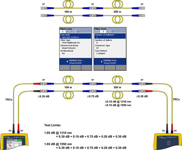
You will note the adapter count has increased to one (since we have one more adapter in the link than when we referenced) and that the middle connection is permitted to be 0.75 dB. That's because the mated connectors in the middle do not involve a Test Reference Cord. These are two random mated connectors.
The DTX CableAnalyzer will calculate the correct test limit (optical loss budget) for you. Changing the number of adapters/splices will of course increase the test limit. Be sure the Number of Adapters is set correctly.
How often should I Set Reference?
The quick answer is; every time you begin to test a series of fibre links. It is critical to continually inspect the TRCs.


