백서
테스트 벤드 둔감 멀티모드 광케이블의 상세정보 (BIMMF): Encircled Flux에 대한 필요
PDF 다운로드
개요
Signal transmission over optical fiber is dependent on the phenomenon of total internal reflection. This happens when light passes from a medium with one index of refraction to another with a lower index of refraction. Due to the difference between the index of refraction of the fiber core (high index of refraction) and the cladding (lower index of refraction), light is guided along the fiber core by constantly reflecting from the cladding. However, when optical fiber exceeds a certain bend radius, some amount of light can be lost, causing signal loss. This can happen during installation or anytime during fiber handling, and is often a concern within the tight spaces of high-density fiber patching areas in the data center.
Several years ago, fiber manufacturers developed ultra-bendable 50 µm multimode optical fiber for use in data centers and enterprise networks. This new bend insensitive multimode fiber (BIMMF) was advertised to withstand tight bends around a 10 mm radius with substantially less signal loss than non-bendable multimode fiber, referred to as non-BIMMF hereafter. With the introduction of BIMMF, installers were finally able to deploy fiber networks without fear of over-bending the fiber and degrading performance. Today, BIMMF is widely deployed in data centers and much has been published about its design and benefits.
BIMMF is laser optimized for high-speed networks and intended for applications with a very tight loss budget. For a typical 10 gigabit Ethernet (GbE) link over 300 m, the allowable channel loss is 2.6 dB. With this strict loss budget, there is little margin for bend-induced loss due to poor installation. Transceivers and test equipment must also ensure a tightly controlled launch, preventing overfill or underfill launch conditions that can further contribute to loss and inaccurate testing. Data provided by fiber manufacturers and test equipment companies has shown that a specific type of launch is required to test BIMMF. This launch condition is encircled flux (EF).
EF is a metric for defining launch conditions on multimode optical fiber that reduces measurement uncertainty in link loss measurements. It was approved in October 2010 with the publication of ANSI/TIA-526-14-B, Optical Power Loss Measurements of Installed Multimode Fiber Cable Plant. EF improves accuracy by specifying the modal power across the entire fiber end face of the launch with the use of a template, which more closely matches the tightly controlled launch conditions of today's gigabit and 10 gigabit Ethernet optical fiber transceivers.
BIMMF Design
To achieve bend insensitive properties, BIMMF uses a different design than non-BIMMF. In non-BIMMF, the glass consists of a core and cladding, each having a different index of refraction. In contrast, BIMMF has a specially engineered optical “trench” added between the core and cladding. This trench contains the propagating modes within the fiber core, even in an extreme bend. It essentially does not allow light to escape from the core.
According to fiber manufacturers, the design of BIMMF is complex and challenging. The refractive index profile must be carefully designed to make sure that all performance parameters meet industry standards. Since fiber bandwidth is one of the important specifications for multimode fiber, the fiber profile must maintain high bandwidth. The design and location of the optical trench is a critical factor. Multimode optical fiber supports many modes of light propagation, including higher- and lower-order modes. Found closer to the outer fiber core, the higher-order mode groups are more sensitive and likely to escape the core during bending. A poorly designed and located optical trench can cause delays in the higher-order light modes and degrade bandwidth. Well-designed BIMMF confines as many of these higher mode groups within the core as possible to maintain optical transmission integrity.
The basic idea of a good BIMMF design is to tightly confine the higher-order mode groups within the fiber core. Non-BIMMF can typically support 17 key mode groups. BIMMF that is designed to also support 17 mode groups results in better compatibility with OM3 and OM4 fiber. One way to examine the quality of the BIMMF design is to test the difference between BIMMF and non-BIMMF using the encircled flux method. The difference in the encircled flux results between a non-BIMMF and a well-designed BIMMF should be small.
All BIMMF designs exhibit a length dependency for the fiber core diameter and numerical aperture if an overfilled launch is used. Higher-order modes that get launched into the trench can remain there for some distance until they attenuate. These modes that are captured and propagate within the trench area are referred to as “leaky modes.” This phenomenon affects splice and connector loss. On the other hand, non-BIMMF does not have a length dependency. An encircled flux launch mitigates the core diameter and numerical aperture length dependency for all BIMMF designs. Further, an encircled flux launch accurately depicts the system performance.
Modal Power in Fiber
After the patents were filed, fiber manufacturers disclosed that bend improvement is achieved through the use of the aforementioned optical trench that prevents higher order modes from leaving the fiber core. In an early testing performed by one fiber manufacturer, it appeared that BIMMF supported more mode groups than standard fiber. These extra modes change the way light couples into and out of the fibers, which can be seen with the encircled flux test method.
When testing standard fiber, accuracy can be achieved with a dual wavelength source and a common test cord and mandrel. With BIMMF, a standard 25 mm mandrel will not strip out the higher order modes at 850 nm, resulting in pessimistic losses. More turns around a smaller 4 mm mandrel are needed to achieve accurate testing for BIMMF at the 850 nm wavelength, but the same mandrel cannot be used for testing BIMMF at the 1300 nm wavelength.
Attempts to produce a more controlled launch using BIMMF for the launch cord proved difficult for two reasons. First, the mandrel design required a very small and uniquely shaped outside diameter. Testing on different manufacturers' BIMMF showed that while the 850 nm source could be accurately tested with a specially designed mandrel, the 1300 nm source could again not use the same mandrel. According to the EF properties of mode control, this indicated a predicted divergence in the loss readings between the two wavelengths when compared to standard fiber.
론치 조건
When testing multimode fiber links, attenuation measurement is greatly influenced by the launch condition of the light source. If a test is performed with two different sources having a different launch condition, the attenuation measurement could vary significantly. Not only will testing be inconsistent, it will produce confusing results. A link tested with an underfilled launch may not detect high loss events such as a misaligned connection, causing the potential for a bad link to pass. To achieve a consistent and accurate measurement, all launch conditions need to be standardized. The importance of an encircled flux launch cannot be overstated.
Launch Cord Selection – International standards for multimode testing sets precise launch condition metrics using encircled flux for testing installed multimode fiber cabling attenuation. Suppliers of test equipment generally provide a dual wavelength source with a common mandrel or mode conditioner. While compliant launches are achievable from dual wavelength (i.e., 850 nm and 1300 nm) sources with the same mandrel wrap on non-BIMMF launch cords, data presented at a TIA fiber standards meeting showed that the targets of a common mandrel and alignment of launch appear to diverge if attempting to use BIMMF as the launch cord. A common mandrel appears not possible given the large wavelength dependence of fiber bend loss. Unless these issues can be mitigated, BIMMF should not be used in launch cords.
Receive Cord Selection – To complete a permanent link test using the recommended 1-cord reference method, a receive cord must be used. The purpose of the receive cord, as well as the launch cord, is to provide link attenuation measurements that include the installed fiber plant and the two connections at each end of the link. For a well-designed BIMMF test cord that matches the installed cabling core diameter and numerical aperture, it may not matter if a BIMMF or non-BIMMF receive cord is used. However, to avoid the possibility of an overly optimistic test result using BIMMF test cords, it is prudent to also use a non-BIMMF as the receive cord.
Compatibility with Non-BIMMF
According to most fiber manufacturers, BIMMF is fully compatible with OM2, OM3 and OM4 standards for laser-optimized multimode fibers and is also backward compatible with the installed base of non-laser-optimized 50 µm multimode fibers. The compatibility and performance is dependent on the design of BIMMF.
In 2011, a leading fiber supplier carried out extensive modeling and experimental tests on BIMMF. These tests showed that optimized BIMMF is backward compatible, has low macro bend loss and exhibits a similar differential mode delay as standard non-BIMMF. Experimental and modeling tests showed that BIMMF can be mixed with non-BIMMF without inducing excess loss.
Fiber splice loss is strongly dependent on the number of guided modes and their mode field shapes. Splice loss is minimized when the number of modes and mode field shapes are matched. This means that a controlled EF launch is needed and that fiber core size and tolerances are matched. EF is maintained at a splice between non-BIMMF and BIMMF when core size and tolerances are matched.
Below is an excellent summary provided at a TIA standards meeting from a leading fiber manufacturer in a question and answer format regarding BIMMF and non-BIMMF compatibility (test data not included herein):
1. Question: Does a homogenous BIMMF link exhibit equivalent insertion loss to that of legacy multimode fiber? Answer: BIMMF designs exhibit lower insertion losses than legacy multimode fiber.
2. Question: Does a heterogeneous BIMMF link exhibit equivalent insertion loss to that of legacy multimode fiber? Answer: Concatenating different BIMMF from the same design has minimal impact.
3. Question: Does a mixed cable link of different BIMMF designs exhibit equivalent insertion loss to that of legacy multimode fiber? Answer: Insertion losses are comparable when different BIMMF designs are concatenated.
4. Question: Does mixing BIMMF with legacy multimode fiber exhibit equivalent insertion loss to that of legacy multimode fiber? Answer: When BIMMF designs are mixed with legacy multimode fiber, insertion losses are less than the legacy multimode fiber only.
테스트 방법
Now let's take a closer look at the test methods for BIMMF, which are really no different than testing other fiber types with a few exceptions. Testing multimode fiber cabling containing BIMMF always requires a launch cord attached to the light source used during the test and a receive cord when measuring a permanent link. Below are the three basic recommendations for testing BIMMF based on testing and general consensus from fiber experts:
1. Use an encircled flux launch with a non-BIMMF launch cord
2. Use the 1-cord reference test method
3. Use a non-BIMMF receive cord for permanent link testing
It may be more important to use a receive cord that closely matches the fiber under test instead of prescribing a fiber type. This is similar to a situation where core sizes are mixed when testing. The effect of interconnecting BIMMF to non-BIMMF when not matched by design is similar to connecting two fibers of different core diameters or numerical aperture. When light passes from a smaller core diameter to a larger diameter, attenuation will be lower than if light passes from a larger core diameter to a smaller diameter. However, to play it safe, a non-BIMMF receive cord is recommended.
Figure 1 shows a generalized three step process for measuring and validating the attenuation of a short test cord. In Step 1, the output power of the non-BIMMF launch cord is zeroed using an optical power meter with a large area photodetector. In Step 2, side “A” of the test reference cord (TRC) is measured. Finally in Step 3, the “B” side of the test cord is measured.
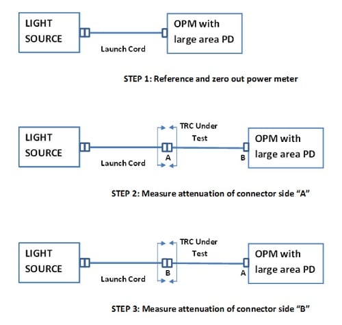
Figure 1 – General method for testing a short test cord
Figure 2 shows a generalized two-step process for measuring and validating the attenuation of a permanent link. In Step 1, the output power of the non-BIMMF launch cord is zeroed using an optical power meter with a large area photodetector (1 mm or larger). In Step 2, the receive cord is added to the far end of the cabling plant. All test cords are done using non-BIMMF. The final attenuation measurement is then made.

Figure 2 – General method for testing a permanent link
Figure 3 shows the complete four-step test that includes the reference, validation of the receive cord and the actual permanent link test using an encircled flux launch on a non-BIMMF launch cord and on a non-BIMMF receive cord. The cabling under test can be BIMMF, non-BIMMF, or a mixture of the two.
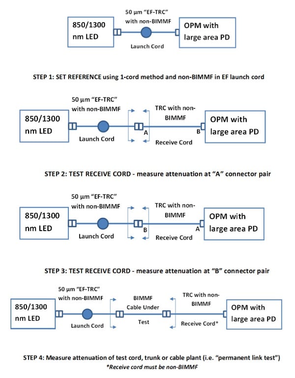
Figure 3 – Four step process for testing a permanent link
요약
BIMMF allows cabling installers to deploy a network with less worry about inducing bend loss due to workmanship. BIMMF is comparable and compatible with other non-bend insensitive multimode fiber such as OM3 and OM4. However, the design of BIMMF is critical for achieving good compatibility.
For proper operation of BIMMF links, either homogenous or mixed with legacy fiber, it is important to use a more tightly controlled launch – encircled flux. An overfilled launch will trap more high-order modes in the trench (i.e., leaky modes) and performance will be compromised. Since it is difficult to use BIMMF with a mandrel and as a launch cord, and because a common mandrel produces skewed wavelength results, non-BIMMF should be used for the launch cords.
The one-cord reference method will provide the most accurate measurements when testing short test cords made of BIMMF or a link containing BIMMF. It is recommended that non-BIMMF be used as the receive cord when measuring permanent links. Doing so will prevent overly optimistic results for a less than ideal BIMMF design.


