PoE 부하 테스트: PoE 시스템을 위한 고급 문제 해결
2021년 7월 27일 / General, Installation and testing, Upgrading and troubleshooting, Best Practices
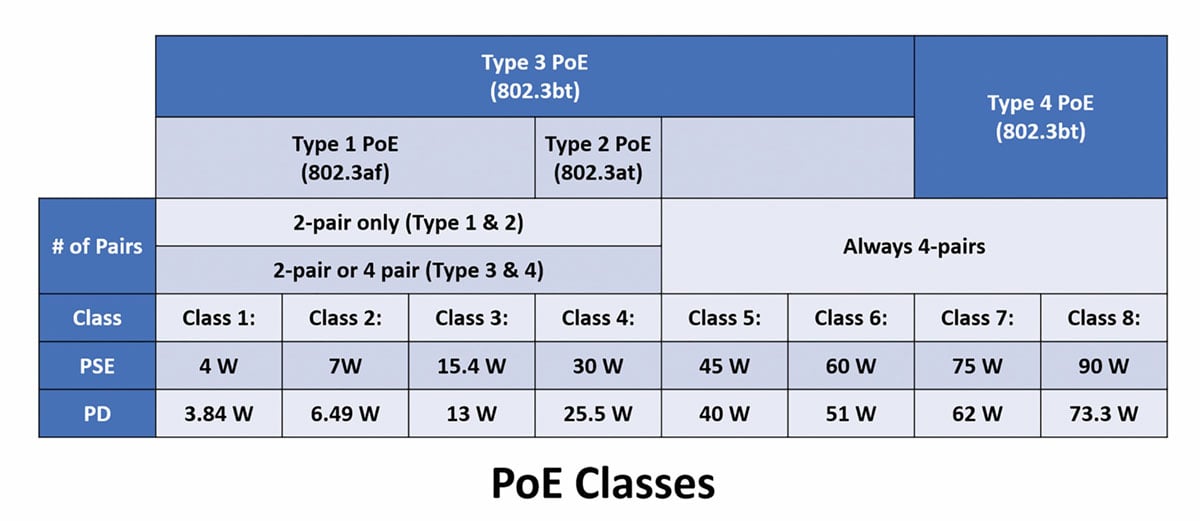
Since the original IEEE 802.3af Type 1 power over Ethernet (PoE) standard that delivered up to 15.4 Watts (W) was first introduced in 2003, the technology has evolved to include Type 2 (up to 30 W), Type 3 (up to 60 W), and Type 4 (up to 90 W). That means PoE voltage now supports everything from phones, Wi-Fi access points, and surveillance cameras, to laptops, digital displays, and even facility-wide LED lighting—all requiring various levels of PoE power.
To help manage PoE requirements, IEEE also assigns classes to PoE systems that range from 0 to 8. Type 1 and Type 2 PoE encompass Class 0 through Class 4 (4–40 W), Type 3 includes Class 5 (45 W) and Class 6 (60 W), and Type 4 includes Class 7 (75 W) and Class 8 (90 W). That essentially means you could have 8 different classes of PoE devices supported by a single PoE switch or other power sourcing equipment (PSE). And when one of those devices isn’t getting power, you need the ability to troubleshoot it.


PoE Not Working?
There are a variety of reasons why a PoE device might not be working. Lack of continuity due to poor terminations such as opens, shorts, and miswirings, as well of cable damage along a link, can obviously prevent any signal—data or PoE—from transmitting. Increased insertion loss due to heat rise or poor DC resistance unbalance performance can also be a culprit, as well as a device that is not compliant with IEEE PoE standards. When a link has passed certification testing, you have verified continuity, and a standards-compliant PoE device is still not receiving power, the problem could be the active power sourcing equipment (PSE).
On a PoE-enabled switch, the amount of PoE power is allocated per port based on the requirements of its connected device. Allocation allows the switch to supply power with greater efficiency. For example, a typical 24-port PoE-enabled switch may have a power budget of 740 W for powered devices, enabling up to 30 W (Type 2) on each port. With such a wide variety of PoE devices now residing on the network, it’s pretty much guaranteed that not every connected device will require the full 30 W from the switch—you could have a VoIP phone requiring just 7 W of PoE power from one switch port and surveillance camera requiring 15.4 W on another switch port.
Through allocation, the amount of PoE power delivered on a specific port can be reduced. By the same token, PoE power can be increased on a port to support a device that requires more power. The basic rule of thumb is: for a connected device to receive an adequate level of power to operate, the PoE power delivered via the PSE must be equal to or greater than the class of its connected device. For that to happen for all devices connected to the PSE, the total power required for all the devices cannot exceed the total power budget of the PSE.
While today’s advanced PoE switches can determine power requirements of connected devices via power-negotiation messages and allocate power appropriately, problems can arise when that communication malfunctions, PoE has been manually (and incorrectly) allocated per port, the overall power budget of the switch has been oversubscribed, or the equipment can’t support the device requirements. And that calls for more advanced troubleshooting.
How to Check PoE on a Switch Port

Network switches use standards-based link layer discovery protocol (LLDP) or Cisco discovery protocol (CDP) that allow them to discover connected devices and advertise their capabilities. These protocols can be used to acquire information about a switch and a specific port, including port ID, VLAN, advertised speeds, and PoE. Fluke Networks LinkIQ Cable + Network Tester has the ability to receive discovery protocol packets from a switch for a given link and place a load on the connection to ensure that the advertised power is actually what is being delivered across the cabling to the device. This is referred to as PoE load testing.
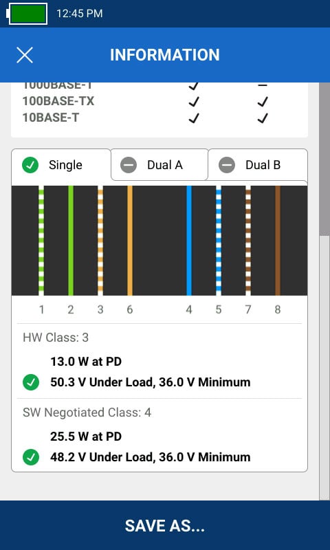
As a PoE load tester, LinkIQ shows which pairs of a four-pair network cable are carrying power, the negotiated power class (0-8) and the loaded power in watts provided by the PSE at the device. It also shows the minimum required volts that the device needs to meet under load based on the negotiated power class and the actual measured volts under load to ensure it meets that requirement. Because power negotiation between the PSE and PD occurs both at the hardware and software levels to ensure that a device has the capability to connect to the network and to allow for dynamic allocation by the PoE switch, LinkIQ shows this information for both the hardware and software class. A PoE device fails testing with LinkIQ if its negotiated hardware or software class is greater than the power the PSE can deliver. It also fails if the PSE cannot deliver power to the device because the maximum power which the switch can deliver is already in use—in other words, the power has been oversubscribed.
LinkIQ shows you how to check if a switch is PoE enabled and even indicates if the switch can negotiate single signature power or dual signature power. A single-signature device maintains the same power signature across both pair sets (pairs 1,2 and 3,6 and pairs 4,5 and 7,8) while a dual-signature device can have independent power signatures on each pair set, either 1,2 and 3,6 (Dual A) or 4,5 and 7,8 (Dual B). This information is useful because IEEE 802.3bt (Type 3 and Type 4) supports both topologies, and if your switch only supports single-signature devices, it may need to be updated to support dual-signature 802.3 bt devices.
While certification testing will tell you if an installed cabling plant will support PoE and simple wiremap testers will identify continuity issues, once active devices are installed, Fluke Networks LinkIQ with its switch negotiation and PoE load testing capabilities is ideal for more advanced PoE testing.


