MHz vs Mbits and Encoding
- MHz: A unit of frequency, describes electrical signals. Pertains to the Physical Medium
- Mbits: A data rate, describes throughput achieved by the system (electronics, software and medium)
Time for a story
Once upon a time, I was very happy if I could get my modem to work reliably at 4800 bps, as a matter of fact, I was ecstatic if got connected at 9600 or 9.6 kbps. Now I am using a 56 kbps modem that seems to do just fine (although you never get connected at exactly 56k). The phone line to my house hasnt changed; it still the same copper wire. The signal encoding (standard V.90) combined with error correcting codes and compression has made this faster data transfer possible and even more reliable. A similar scenario is unfolding for Gigabit Ethernet over Cat 5.
Digital Signal Encoding

"Man" in the second line designates "Manchester" encoding which is used for standard Ethernet. The bottom line depicts "Differential Manchester" encoding which is very similar (but different, as you can see) and is used by Token Ring. In both Manchester systems, the signal goes through a transition from high to low or the opposite direction in the middle of each bit time slot. This transition guarantees good synchronization between sender and receiver. Therefore, people sometimes state that 10BASE-T runs over "barb wire". Indeed it uses a very robust signal encoding technique. But also note that the Manchester signal encoding goes through roughly twice as many level changes per time as the NRZ signal above. Therefore, Manchester encoding is very inefficient as far as bandwidth requirements. To transmit 10 Mbps you need at least a 10MHz bandwidth for the signal on the cable. (That is a very bare minimum. Fortunately, Cat 3 behaves pretty well up to 16 MHz.)
Obviously, to get higher data rates over twisted pair cabling, we had to find other signal encoding systems that could still provide for reliable synchronization. One such system is the 4 bit- 5 bit encoding. Every four bits of data are translated into a sequence of 5 bits for transmission. Five bits provide 32 different combinations. Out of these 32 combinations only 16 (half) have to be selected for data encoding. We can select those 5-bit sequences that provide the maximum number of "transitions" for good synchronization. For example 00000 and 11111 will be excluded, for sure.
Some additional advantages are listed: we can utilize the remaining 16 codes for delimiters or idle patterns, and if an "illegal" pattern appears, we have detected that the cable transmitted something in error. The data stream has grown 25% though. To transmit 100 million bits of data, we need to transmit 125 million signal on the cable and signal level is valid for 8 nsec. To contain the bandwidth requirement for this signaling rate. The signaling uses a "pseudo-ternary" encoding. This is not a tri-level logic signal but instead, we will chose 0 volt for a signal that represents a logical 0. The logical 1 signal will "toggle" between +1V and -1V. See below. It will appear intuitive that fewer signal transitions are required per unit of time. There is also a mathematical proof for the signal bandwidth requirements.
100BASE-TX Signal Encoding
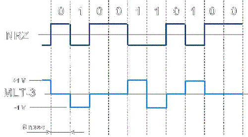
We will explain a four-level signal encoding. Gigabit Ethernet actually uses PAM-5, a five level encoding scheme. The "fifth" level is used for additional synchronization as well as error detection/error correction. Note that the signal timing is 8 nsec which is exactly the same value as we encountered in Fast Ethernets 4B-5B encoding.
The signals on the cable can take five different levels while the total voltage swing from min to max is still the same 2V swing (from -1V to +1V). The signal levels are no longer separated by 2V, but by 0.5 V. The direct result of this separation is that if a noise spike of 0.25V hits the cable, the receiver will most likely not be able to determine which signal level had been transmitted. This situation is somewhat alleviated by the error detection/error correction encoding level.
Four-level Signal Encoding
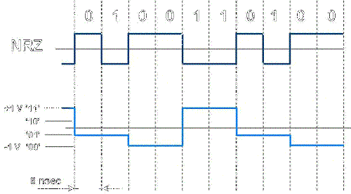
This is an example of what a four-level encoding scheme might look like. Remember this illustrates the type of signal encoding used in 1000BASE-T. The real encoding system is called PAM-5, which is a five-level system.
Nyquist theorem for a noise-free channel
To throw some theory into the picture. You may have heard of the Nyquist frequency. Here is the explanation in short. Shannons law applies to predict how much bandwidth needs to be available above the Nyquist minimum based on the expected signal-to-noise ratios.
Limitation determined by signal bandwidth R=2Wlog2M
Where R is the rate of data transmission, W is the maximum frequency and M is the number of levels of encoding
Example 1: 10BASE-T
This is a two level encoding so M=2,
Therefore the bandwidth (W) = R / log22 * 2 which gives 10MHz (Remember that throughput of 10BASE-T is 20Mbits)
Example 2: 1000BASE-T
This is a four level encoding so M=4 (5th Level is for synchronization only)
Therefore the bandwidth (W) = R / log24 * 2 which gives 62.5MHz (R = 250Mbits/s)
This is theory, and in real life the protocol for 1000BaseT needs a little more typically 80MHz, so the IEEE specifies cable testing on all pairs up to 100MHz.

Transmission performance for Cat 6 components and installations needs to be verified to 250 MHz. Using the ACR model of bandwidth, the installation is predicted to have a positive margin similar in the size to the margin of a Cat 5 installation at 100 MHz. At 250 MHz the installation will have a negative ACR margin. The IEEE has been the instigator to encourage testing to 250 MHz with an eye on the possibility that the continued development of DSP technology will allow transmission beyond the ACR bandwidth. Recall that this technology had initially been developed for 100BASE-T2, which never was implemented. The 1000BASE-T standard relies heavily on these DSP techniques to guarantee reliable transmission over Cat 5. MHz Mbits MHz Mbits MHz Mbits MHz Mbits MHz Mbits MHz Mbits MHz Mbits
The development of One-Gbps Ethernet started out within the IEEE 802.3 committee as the IEEE 802.3z project. However, it became clear that the development of the 1000BASE-T (100 m on category 5) would require more work and was going to be delayed relative to the fiber and short-haul (25 m) copper solution. Since Gigabit Ethernet would first find application in the backbone where fiber is the predominant medium it made good sense to split the two efforts and expedite the fiber solution.
Therefore a separate project IEEE 802.3ab was created to specifically address 1000BASE-T development.
-
1000BASE-LX (long wavelength: >1300 nm)
MM Fiber up to 550 m
SM Fiber up to 2,500 m -
1000BASE-SX (short wavelength: 850 nm)
MM Fiber 62.5 m up to 220 m
MM Fiber 50 m up to 300 m -
1000BASE-CS
Short haul copper (25 m)
The short haul copper solution uses (IBM) triax cable, and is intended only for backbone applications in an equipment room --interconnecting of hubs or other networking electronics in an equipment room. It is definitively not considered part of a generic cabling solution. It is expected that these short haul copper cables will be factory produced in fixed lengths.
This portion of One-Gbps Ethernet was approved June 1998. The fiber standards development encountered some remaining issues with modal bandwidth resulting in excessive jitter on multimode fiber. This resulted in the definition of the maximum distance on MM fiber as shown above. The modal dispersion and resulting jitter is a function of the diameter of the core and the wavelength (and spectrum) of the light source.
IEEE 802.3ab is now fully devoted to One-Gbps Ethernet on category 5 twisted pair cabling. All 4 wire pairs in the standard four-pair cable are used, and transmission is full duplex on all 4 wire pairs. NEXT cancellation techniques are also implemented. This technique was first developed (but never implemented) for the proposed 100BASE-T2. The latter was defined as a two wire-pair solution on category 3 for Fast Ethernet (100 Mbps data rate). A five level encoding system was adopted; it is called PAM-5, more about this later. The initial goal of the IEEE 802.3 committee was to obtain a completed standard by late 1998; delays over Return Loss caused a delay. It was however resolved an agreed in August 1999.
The IEEE 802.3ab working group requested assistance from the TIA TR41.8.1 UTP task group to fill in requirements needed for One-Gbps operation over category 5 cabling. (Note that in December 1998 the name of this TIA group changed to TR.42.)
This task group has adopted a "fast" track project to do so, and the goal was to match the timeline for 1000BASE-T. Both projects have "slid" together. It is emphasized in every possible way that it is expected that the existing -- and currently installed -- category 5 cabling should normally meet the additional requirements, which were previously left unspecified. As a result, the TIA will still call the newly compliant cable "category 5", and not anything like "category 5e" or "category 6". The Cat 5 specifications have been amended with a recommended performance level for the new test parameters (FEXT-related measurements and Return Loss). The recommendations are specified in a Telecommunications Systems Bulletin (TSB95). TSBs dont have the weight of a "standard"; they are recommendations. (TSB67 was an exception; it has the normative weight of a standard.)
We are saying that the ultimate measure of success in data transmission is the fact that frames are successfully transmitted. There are no bit errors (no FCS errors) and no re-transmissions. The physical layer plays a critical role in achieving error free transmission on the data link layer. The bandwidth characteristics of the physical layer must match the requirement of the physical signal encoding used by the network.
(1) We need to explain the basic ground rules for all of the "frequency" plots we will be using during the discussions of the standards and especially to describe the performance of parameters that vary with the frequency such as NEXT and attenuation. In the frequency domain, we plot frequency along the horizontal axis and we show "something" about a signal with that frequency in the vertical axis. The simple example below represents at the left side how a pure sinusoidal frequency signal varies in time. If we assume that the period is 1 microsecond, the signal will repeat one million times per second or is called one megahertz (MHz). In the time domain plot on the right, we represent the amplitude of that signal.
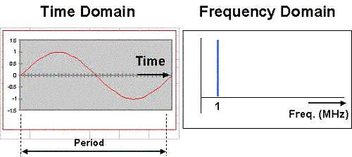
The beginnings of the Fourier analysis
(2) We have a second goal. To lay the groundwork to explain that digital signaling contains a multitude of frequencies and that the transmission medium needs to do an "adequate job" -- defined by a standard -- for all the frequencies of interest.
Lastly, this set of drawings may be used to introduce the digital test technique. The DSP Series testers from Fluke send pulses that contain many frequencies.
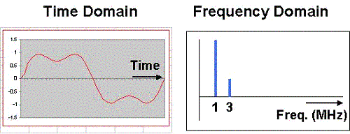
Add two sinusoidal signals to get the time domain signal depicted in the left-hand side plot. We have added to the 1 MHz signal of the previous slide a signal of 3 MHz with amplitude equal to 1/3 of the 1 MHz signal. The frequency domain picture above shows the two frequencies each with its amplitude value.
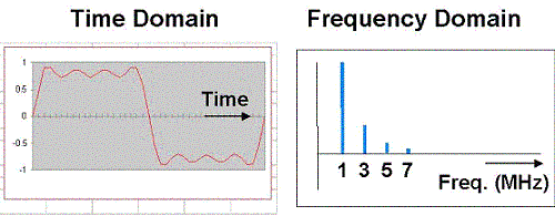
We now have added 4 signals together. The signals with higher frequencies, called harmonics, have successively smaller amplitudes: 1/3, 1/5, 1/7, etc.. You can see that the time domain picture is approaching digital signaling, i.e. two distinct voltage levels.
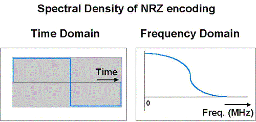
Finally, we are ready to flip the whole thing into the other direction. In theory, we are transmitting the digital signal shown in the time domain picture, a perfect square wave. The frequency domain shows that such a digital signal contains a number of frequencies. As a matter of fact, every frequency between 0 and some upper value is represented. For a two-level digital signal, the upper value is the frequency equal to the data rate.
예: using the NRZ encoding for ATM 155, this null point is at 155 MHz. Shouldnt we test to 155 MHz? The signal created by the transmitter does not exhibit the perfect rise and fall times that you see in the theoretical model. Changes from one voltage level to another require a finite amount of time (measured as the rise and fall times). The frequency spectrum of the "real" ATM NRZ signal is such that the "tail" in the frequency domain picture drops dramatically. It has been debated by several people as to how much energy is really present above 100 MHz. The second issue to remember is that the receiver may not need or expect any frequencies above 100MHz to properly decode the digital signal that is transmitted.
Megahertz (MHz) is not equal to Megabits per second (Mbps)

