What is (+All) and When Should I Choose It?
May 1, 2019 / General, 101 learning, Installation and testing, Industrial Networks, Best Practices
When it comes to testing twisted-pair cabling, there are some key testing parameters required for certifying a permanent link to industry standards—parameters like insertion loss, NEXT, PSNEXT, ACR-N, PSACR-N, ACR-F, PSACR-F and return loss. And when it comes to testing Cat 6A (or Class Fa for ISO11801 standards), we also have PSANEXT and PSAACR-F for alien crosstalk testing.
While the required parameters are automatically tested for your chosen test limit, have you ever noticed the (+All) suffix on your Fluke Networks’ DSX CableAnalyzer™ Series Test Limits Screen and wondered exactly what that meant and why and when you should choose it? If so, you’re probably not alone.
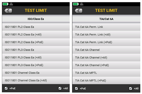
The most recent release of DSX code, 6.1, simplifies the presentation of limits and features both a “+PoE” and “+All” selection at the bottom of many of the TIA and ISO limits. If those are not checked, only the field test limits are shown. Select them, and the list gets longer with “(+PoE)” “(+All)” versions of measurements added to the lists.
When you choose a test limit with a (+PoE) or (+All) suffix, you’re essentially adding additional test parameters not required by ANSI/TIA or ISO/IEC for field testing. For “+PoE”, those measurements are DC Resistance Unbalance within a pair and DC Resistance Unbalance between pairs, as well as a limit for DC Loop Resistance. “+All” includes these along with ELTCTL, TCL, CMRL and CDNEXT measurements. While these additional measurements are not required for field testing, many of these parameters are required for manufacturers to establish compliance, which is why you will find them listed on cabling spec sheets.
While you may not need to test to these limits for certification purposes, and they do add slightly to your test times, they can provide additional insight into your cabling plant performance. Let’s take a closer look to help you decide whether or not to choose (+PoE) or (+All).
(+PoE) DC Resistance Measurements
It’s basic physics - too much resistance in the cabling can cause loss and reduce the amount of PoE power available at the powered device. When you select (+PoE), the DSX will generate a pass/fail result based on the loop resistance of each pair. Loop resistance is measured in any case, but only compared against limits when (+PoE) or (+All) limits are selected.
Selecting (+PoE) or (+All) adds additional PoE-related resistance measurements – here’s why. In 2-pair PoE applications, power is transmitted by applying a common-mode voltage that evenly splits the current between each conductor of the pair. To achieve common mode, the DC resistance of each conductor in the pair must be equal, or balanced. Any difference in resistance between two conductors is referred to as DC resistance unbalance. When there is too much unbalance in the pair, Ethernet signals can become distorted, causing bit errors, retransmits and even nonfunctioning data links. For four-pair PoE applications (Type 3 and Type 4), it’s no longer just the DC resistance unbalance on each pair that matters. Excessive DC resistance unbalance between multiple pairs can cause PoE to stop functioning.
ANSI/TIA, ISO/IEC and IEEE standards specify test limits for loop resistance, resistance unbalance within a pair and between pairs because it’s required by manufacturers for compliance. Before the DSX, no field tester could measure these parameters, so the requirement was not included in field testing. However, improper installation techniques can impact resistance performance, and these tests add no more than a second to the total test time, so a strong argument can be made for performing them in the field – especially for links where you’re likely to use PoE. To learn more, click HERE to read the white paper.
As the name implies, (+All) adds the PoE measurements - and more, which we’ll discuss next.
TCL and ELTCTL
Ethernet signals are applied in differential mode and noise signals are applied in common mode. When noise is injected into a cable, a portion of this common mode signal can be converted to differential mode and become a part of the Ethernet signal. This phenomenon referred to as mode conversion is not a good thing for an Ethernet signal.
TCL (Transverse Conversion Loss) and TCTL (Transverse Conversion Transfer Loss) are the two parameters used for measuring mode conversion. TCL measures mode conversion within a pair at one end and TCTL measures mode conversion within a pair at the opposite end. However, because the amount of common mode signal in TCTL testing is dependent on the length of the link due to insertion loss, equalization must be applied using ELTCTL (Equal Level TCTL).
TCL and ELTCTL only add about 6 seconds to your test times, and they are excellent indicators of noise immunity and whether a cable link will provide adequate performance in noisy environments – including alien crosstalk from neighboring cables or noise from other external sources such as those found in industrial environments. So if you’re installing in noisy environments and need an easy way to determine noise immunity, you might want to select (+All). Plus it can give you peace of mind in manufacturer claims, and it’s ideal for troubleshooting – failed TCL and ELTCTL can cause bit errors and retransmissions even when the other required transmission parameters provide good margins above the standard limits.
CDNEXT and CMRL
CDNEXT (Common Mode to Differential Mode Near-End Crosstalk) is a troubleshooting-only parameter that is not required by manufacturers and has no test limits specified in TIA or ISO/IEC standards. It is however referred to in TSB-1197 “Mode Conversion Parameters for Balanced Twisted Pair Cabling” to help cabling professionals better understand the impact of noise on twisted-pair cabling, including alien crosstalk and other external sources.
CDNEXT is the difference between a common-mode voltage applied to a pair and the differential mode
voltage measured on other pairs at the same end of the cabling. Better CDNEXT values correspond to better noise immunity and lower emissions. Since CDNEXT occurs mostly in connecting hardware, poor CDNEXT is primarily a connector choice issue and can indicate lower quality. While unlikely, it could also be a workmanship issue.
CMRL (Common Mode Return Loss) is the difference between the power of a common-mode signal applied to a pair and the power of the common-mode signal reflected back. These signal reflections are caused by variations in the cable’s impedance and are probably only worth analyzing for a cabling plant that may need to support transmission speeds beyond 10 Gig – although again, it is not required by manufacturers and has no test limits specified in industry standards
Now that you know what the (+PoE) and (+All) suffixes mean on your DSX CableAnalyzer Series tester, you can decide whether or not you want to add these measurements. Since they’re not required for certifying a link, it’s really left up to the decision of the installer or the customer.
최근 게시물 모두 보기 >
네트워크 및 케이블 테스트를 위한 최고의 가이드
2025-5-29
Wi-Fi 7 대 Wi-Fi 6: 새로운 기능 및 네트워크에 대해 갖는 의미
2024-11-25
Versiv™ 릴리스 6.12, 시간 절약, 정확도 향상, 재테스트 감소
2024-10-14
제3자 네트워크 케이블 인증: 알아두어야 할 사항
2024-9-18
삽입 손실 대 반사 손실
2024-8-14
추가 일반 게시물 모두 보기 >
Top 10 Cable Testing Mistakes to Avoid
2025-6-05
네트워크 및 케이블 테스트를 위한 최고의 가이드
2025-5-29
VSFF 커넥터에 대해 알아야 할 사항
2025-5-27
DC 저항 불균형: 알아두어야 할 사항
2025-5-20
LinkIQ™ Duo로 Wi-Fi 분석을 간소화하는 방법
2025-1-28


©2006-2021 Fluke Corporation。保留所有权利。
RM2011, 20/F, SCITECH Tower, 22 Jianguomenwai Avenue, Chaoyang District, Beijing, China
地址:北京市朝阳区建国门外大街22号赛特大厦20层2011室
联系电话:400-8103435
沪ICP备11037028号-15![]()