Single-Mode Fiber is On Rise. 준비가 되셨습니까?
2019년 3월 8일 / General, Standard and Certification, Installation and testing, Industrial Networks
Many of you are likely seeing an increased use of single-mode fiber among your customers due to several benefits (primarily distance and bandwidth), connection to carrier networks, and emerging single-mode applications in development.
With single-mode the de facto standard in outside plant carrier networks and hyperscale data centers, the growing demand for low-cost single-mode transceivers is driving down cost. Plus, we’re now seeing data centers of all sizes gearing up to support speeds of 200 Gig and beyond over single-mode fiber with short-reach applications like 100GBASE-DR, 200GBASE-DR4 and 400GBASE-DR4 that support 100, 200, and 400 Gig to 500 meters.
So sooner than later, you’re going to need to know what it takes to make sure these systems can support the higher speeds your customers require.
Performance Considerations
While it used to be that longer-reach single-mode applications like 100GBASE-LR4 allowed for greater insertion loss, with less-expensive transceivers comes a reduced insertion loss allowance. Compared to the 6.3 dB allowed for 100GBASE-LR4 that supports 100 Gig up to 10 kilometers, we’re looking at just 3 dB for short-reach 100GBASE-DR applications up to 500 meters. So now just like 100 Gig multimode applications, designers need to be aware of their loss budgets, which could limit the number of connections in the channel.
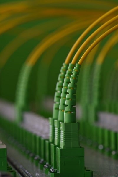
With single-mode fiber and higher data rates, return loss is more of a concern. Too much light reflected back into the transceiver can cause bit errors and poor performance. That’s why we’re also seeing an increased use of angled physical contact (APC) style connectors, where the 8-degree angled end face causes reflected light to be absorbed into the cladding, thereby reducing back reflections in the fiber core.
A New Angle on Cleaning
When it comes to single-mode fiber, there are some key considerations. First of all, single-mode is more difficult to keep clean than multimode. A speck of dust on a 62.5 or 50µm multimode fiber core blocks a lot less light than on a 9µm single-mode fiber core.
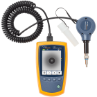
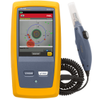
And when it comes to APC single-mode connectors, there’s more to know. When inspecting, you want to make sure to use an APC inspection probe tip designed to direct the camera to match the angle of the APC connector. The Fluke Networks FI-7000 FiberInspector™ Pro and FI-500 FiberInspector Micro have an APC probe tip available for purchase.
For APC connectors, you also want to make sure that the entire end face surface comes into contact with your cleaning apparatus. In other words, the cleaner must be aligned at the same 8-degree angle of the connector for proper cleaning.
Testing it Right
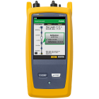
When it comes to Tier 1 testing of single-mode fiber with APC connectors, you also want to make sure you use an APC adapter. On the Fluke Networks CertiFiber® Pro, this is only an issue on the output port, as the input port is non-contact mating.
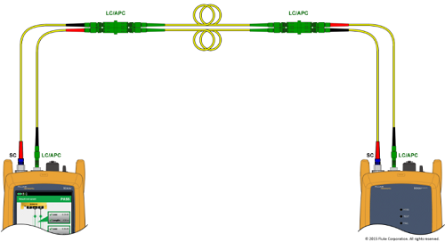
While no damage will occur if you connect an APC connector to the input, you will get a warning about the received power being too low. To test APC systems, you will need two hybrid UPC-to-APC cords and two APC-to-APC cords to make the connection. For Tier 2 OTDR testing, since reflections when using APC connectors are absorbed by the cladding and return loss is very small, the Fluke Networks OptiFiber® Pro (in fact all OTDRs) will show APC connections as a non-reflective loss like a splice.
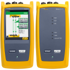
For 200GBASE-DR4 and 400GBASE-DR4 short-reach single-mode applications, you’re also going to be dealing with MPO connectors, as they require 8 fibers with 4 sending and 4 receiving at 50 or 100 Gb/s. That’s where a tester like the Fluke Networks MultiFiber Pro with a dedicated on-board MPO connector that can scan all fibers simultaneously is highly recommended to avoid time-consuming use of MPO to LC fan-out cords that separate the multiple fibers into single fiber channels. And if you do much work with MPO’s, a specialized inspection camera, such as our FI-3000 Fiber Inspector Pro, can be a real time-saver. Of course, it comes with and APC MPO adapter.
And when testing single-mode fiber systems, you also want to make sure you’re testing at both the 1310 and 1550nm wavelengths. If these two wavelengths pass, so will everything in between, but slight bends might not show up at the 1310 nm wavelength.

