Tips for Taking on Tier 1 and Tier 2 Fiber Testing
January 21, 2016 / General, Installation and testing, Upgrading and troubleshooting, Best Practices
Unlike required Tier 1 testing for attenuation (insertion loss), length and polarity that can be achieved with an optical loss test set (OLTs), few technicians in the field find themselves faced with Tier 2 testing and the need for an Optical Time Domain Reflectometer (OTDR).
But every now and then, there is that one customer or consultant who specifies Tier 2 testing—especially as fiber networks have ever-tighter loss budgets and less room for error. Or there may be the need to gain more insight into the performance of a link component for troubleshooting purposes.
Regardless of the reason for taking fiber testing to the top tier, it’s good to understand the technology and best practices surrounding Tier 2 testing.
Not a Replacement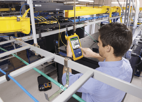
First of all, it is important to acknowledge that Tier 2 testing does not replace the total insertion loss measurements taken during Tier 1 testing. Tier 2 testing requires Tier 1 and is used as a complementary evaluation—using both methods provides the most completed picture of the fiber installation. In other words, just because Tier 2 testing may be required doesn’t mean you can skip Tier 1. You still need to measure the total fiber losses of the link.
However, Tier 2 testing does do something that Tier 1 cannot—an OTDR characterization of the link. OTDRs use pulsed laser diodes to transmit high-power light pulses into the fiber and high-gain light detectors to measure any light reflected back. These measurements detect events in the fiber that either reduce or reflect the power of the source pulse. While a small amount of backscatter is expected in any fiber link, when the light meets a connection, break, crack, splice, sharp bend or end of the fiber, it reflects a certain amount of light expressed in dB.
The OTDR characterization is achieved by plotting the reflected light versus the distance along the fiber, providing a graphical signature for technicians to determine precisely where in the link the reflection occurs—the ideal troubleshooting tool. It is also an extremely useful way to measure the loss of a specific splice or connector within a link to ensure that is no larger than what is required by the standard, that it meets performance values specified in manufacturer claims, or that it is within the range needed to support future applications.
Know the Procedure
The first step in Tier 2 testing is (you guessed it!) to first complete Tier 1 testing. Once you’ve completed Tier 1 testing to verify that the fiber links meets the loss budgets as specified by TIA and ISO/IEC standards for a given application, connect the OTDR to one end of the link using a launch fiber and attach a tail fiber to the connector at the far end.
Similar to using test reference cords when using an OLTS in Tier 1 testing, launch fibers must be used at both ends of the link when testing with an OTDR. The launch cable connects between the OTDR and first connector enabling the tester to overcome dead zone limitations so it can measure the loss and reflectance of the first connector in the link. The tail fiber serves a similar purpose—it allows the tester to properly see and test the last connector at the far end of the link.
Once you’ve configured the OTDR with the appropriate limits and connected both launch and tail fibers, perform your test. Then disconnect the OTDR, leaving the launch and tail fibers in place and connect the OTDR to the far-end tail fiber. Now test a 2nd time to look at the link in the opposite direction. Calculate the average loss of both bidirectional results for the link, compare to the limits, and review pass or fail results.
Easier than You Think
Are you surprised by how simple Tier 2 testing seems? Don’t be. Legacy OTDRs used to require years of technical experience to read and interpret traces, but today’s OTDRs contain comprehensive software that automate analysis and test parameter set-up, among other advanced analytical capabilities.
Fluke Networks’ OptiFiber Pro makes it even simpler to fully characterize your fiber links with its SmartLoop capability. SmartLoop enables automated testing and analysis of two fibers in a single test. This patent pending process automatically separates the two fibers for individual pass/fail analysis, display, and reporting. Not only does this cut the testing time by at least half, it also enables bi-directional testing without moving the OTDR to the far end of the link. In addition to getting the job done quicker, SmartLoop OTDR further enhances the ease and speed of testing in environments where the far end is difficult of even dangerous to reach because the OTDR never has to be moved to the far end.
최근 게시물 모두 보기 >
네트워크 및 케이블 테스트를 위한 최고의 가이드
2025-5-29
Wi-Fi 7 대 Wi-Fi 6: 새로운 기능 및 네트워크에 대해 갖는 의미
2024-11-25
Versiv™ 릴리스 6.12, 시간 절약, 정확도 향상, 재테스트 감소
2024-10-14
제3자 네트워크 케이블 인증: 알아두어야 할 사항
2024-9-18
삽입 손실 대 반사 손실
2024-8-14
추가 일반 게시물 모두 보기 >
Top 10 Cable Testing Mistakes to Avoid
2025-6-05
네트워크 및 케이블 테스트를 위한 최고의 가이드
2025-5-29
VSFF 커넥터에 대해 알아야 할 사항
2025-5-27
DC 저항 불균형: 알아두어야 할 사항
2025-5-20
LinkIQ™ Duo로 Wi-Fi 분석을 간소화하는 방법
2025-1-28


©2006-2021 Fluke Corporation。保留所有权利。
RM2011, 20/F, SCITECH Tower, 22 Jianguomenwai Avenue, Chaoyang District, Beijing, China
地址:北京市朝阳区建国门外大街22号赛特大厦20层2011室
联系电话:400-8103435
沪ICP备11037028号-15![]()