백서
Best Practices for Standards-Compliant Fiber End Face Inspection and Cleaning
PDF 다운로드
개요
Inspection and cleaning of fiber optic end faces have been best practices for some time, yet contaminated connections remain the number one cause of fiber-related problems and test failures for data centers, campuses, and other enterprise or telecom networking environments.
As the industry moves to higher data speeds, more stringent loss budgets, and widespread use of multifiber connectors, being proactive about inspecting and cleaning fiber end faces is more critical than ever to ensure network uptime, performance, and equipment reliability.
Every connector end face — whether field terminated or factory terminated — should always be inspected, and cleaned if necessary, before connecting to a component or piece of equipment. However, depending on subjective human inspection of fiber end faces produces inconsistent results. That is why relying on International Electrotechnical Commission (IEC) industry standards and innovative inspection equipment is the most reliable way to ensure automatic, consistent, and repeatable certification of fiber cleanliness based on specific acceptance criteria.
이 페이지의
- A Contaminated End Face Degrades Performance
- The Golden Rule: Inspect Before and After Cleaning
- Inspecting and Certifying with IEC Standards
- Optical Performance Matters Most
- 무엇을 검사하고 청소해야 하는지 알기
- The Best Tools for Cleaning Fiber End Faces
- Don't Let Dirty End Faces Pose a Risk to Your Fiber Network: Inspect Every One
- Fluke Networks Fiber Inspectors Automatically Certify Fiber End Faces to IEC Standards
- Cable Certification with the Fluke Networks Versiv Family
A Contaminated End Face Degrades Performance
Every fiber installation relies on proper end face cleaning practices for good reason. Network performance is only as good as the weakest link, and the weakest link is wherever a fiber end face is exposed — whether at a patch panel, equipment port, or at the end of a patch cord or jumper.
Regardless of the type of fiber, application, or data rate, the transmission of light requires a clear pathway along a link, including through any passive connections or splices along the way. 광케이블 코어에 한 개의 입자가 있는 경우 손실 및 반사가 생겨서 높은 오류율 및 저하된 네트워크 성능으로 귀결됩니다. Contamination on a fiber end face, as shown in Figure 1, can also adversely impact the interface of expensive optical equipment, and even render equipment inoperative in some cases.

그림 1: Dirty fiber end faces like this one can degrade network performance or damage equipment.
The fiber networks at the heart of today’s data center must meet consumer demand for high-speed access to information anywhere and anytime. Downtime and poor network performance are not an option. As network applications demand more bandwidth and transmission speeds climb to 100, 200, 400, and even 800 gigabits per second (Gbps), loss budgets have become tighter than ever. Dirt, dust, and other contaminants are the enemies of these higher-speed data transmission rates — which makes it critical to keep all optical connections free of contamination to avoid application performance issues. Contamination is the single greatest cause of fiber failures. Spending the extra few seconds properly inspecting every connector end face, and cleaning it if necessary, saves time and money in the long run.
Any time an end face is exposed to the surrounding environment, it can be contaminated — even if it was recently cleaned. Accidentally touching a fiber end face and working in dirty, dusty construction environments are known causes of contamination, but there are plenty of other ways to mishandle fiber that can introduce contamination:
- Brushing an end face on clothing that can contain body oils, lint, or other substances can cause contamination.
- Dust in the air can collect on a fiber end face, especially in the presence of static electricity.
- A dirty end face can contaminate a clean end face whenever two connectors are mated.
- Even a dust cover designed to protect the fiber end face can be a significant source of contamination.
Unfortunately, many technicians believe that if an end face has been protected by a dust cover, it must be clean. However, there is no way to know for sure what was in that dust cover, even on new factory-terminated connectors. Dust caps are great at preventing damage to the end face, but the plastic used to create dust caps can emit a residue as it deteriorates over time. The surface of the cap may contain mold-release substances used in high-speed production processes. You may even find a contaminated end face when you remove the protective cap from a connector fresh out of the bag.
Many also think that an end face plugged into a piece of equipment must be clean and can therefore be unplugged and remated without concern — yet this too can cause contaminants to pass from one end face to another. Even if the initial contamination was outside the fiber core, mating can break up a contaminant and cause tiny particles to travel across the end face and redeposit on the core. The same holds true for equipment ports, which are often overlooked as a source of contamination.
The Golden Rule: Inspect Before and After Cleaning
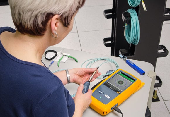
Clean end faces are essential for good performance. The best practice is to inspect fiber end faces both before and after cleaning, using a fiber inspection tool designed specifically for that purpose, such as a professional video microscope or a handheld fiber microscope. Because the very act of cleaning the end face can cause contamination, end faces should only be cleaned if necessary — and then every end face that has been cleaned should be inspected again before connecting. That is one of the golden rules of fiber inspection.
Cleanliness is a special concern for multi-fiber connectors such as the multi-fiber push-on (MPO) connectors that are the norm in data center fiber backbone channels as the required interface for high-speed parallel optic applications like 100, 200, 400, and 800 gigabit Ethernet (GbE) applications (see Figure 2).

그림 2: Always inspect the individual fibers of the MPO connectors required for high-speed parallel optic applications, since it can be difficult to ensure that all fibers in the array are free of contamination.
Consider an 8-fiber MPO interface with an array that features a much larger surface area than a single fiber connector. Contaminants from one fiber can easily migrate to another within the same array, even during cleaning. 그리고 어레이가 클수록 위험이 높아집니다. With 16-, 24-, 48- and 72-fiber MPOs used in high-density fiber interconnects, more fibers are more difficult to control. Not all the fibers always protrude at the same height. 단일 다중 광케이블 커넥터에 있는 광케이블의 높이 차이로 모든 광케이블이 적절하고 동일하게 청소되지 않는 위험을 증가시킬 수 있습니다.
Inspecting and Certifying with IEC Standards
A longtime industry concern with manually inspecting fiber end faces is that determining cleanliness has largely been subjective and inconsistent. What one person considers clean can vary substantially from another person’s point of view. Additional variables such as skill level, years of experience, eyesight, ambient lighting, and the fiber inspection tool being used can also lead to inconsistencies in determining end face cleanliness. With more fiber networks being installed and maintained by a growing number of individuals, there is also a greater chance that inexperience will influence the cleanliness standards they use.
To establish consistency in fiber inspection and achieve more repeatable results for performance across multiple end faces, the IEC developed 61300-3-35, Basic Test and Measurement Procedures for Fiber Optic Interconnecting Devices and Passive Components. This standard defines criteria for minimum microscope compliance, inspection procedures, and specific cleanliness grading criteria to assess pass or fail certification for inspection of a fiber end face, removing the human subjectivity factor.
IEC 61300-3-35 inspection procedures and cleanliness grading criteria vary by connector type, fiber size, and the type of defects. Defects include pits, chips, scratches, cracks, particles, embedded debris, and loose debris. For practical purposes, the IEC standard categorizes defects into two groups: scratches, identified as permanent linear surface features; and defects, which include all detectable non-linear features.
For inspection and cleanliness, IEC 61300-3-35 considers four different zones or regions of a fiber end face (Figure 3):
- Zone A – the core
- Zone B – the cladding
- Zone C – the adhesive
- Zone D – the contact or ferrule
Zone A, where the signal travels, has the most stringent PASS/FAIL requirements, followed by Zone B. Contamination in Zones C and D does not render a FAIL, since scratches and defects in these zones generally do not impede transmission of the light signal through the core of the connector.

그림 3: IEC 61300-3-35 grades fiber cleanliness based on the quality and size of scratches and defects in each region of the end face.
For single fiber end faces, IEC 61300-3-35 recommends starting with inspection of the entire Zone D (contact area) and attempting to remove loose particles that can migrate to the more critical Zones A and B (core and cladding). This process requires a microscope with a small field of view (SFOV) of at least 250 μm and the ability to detect defects of 2 μm in diameter and scratches 3 μm wide.
For rectangular array connectors like MPOs, IEC 61300-3-35 recommends inspecting the entire ferrule and attempting to remove loose particles before inspecting Zone A and Zone B on individual end faces. MPO는 표면이 훨씬 더 크며, 덮개의 어느 곳에서나 느슨한 입자가 개별 광케이블 종단면으로 이동하여 삽입 손실과 복귀 손실을 증가시킬 수 있는 에어 갭을 야기할 수 있습니다. To inspect the entire ferrule for MPOs, IEC 61300-3-35 permits microscopes with a large field of view (LFOV) of at least 6.4X2.5 mm and the capability to detect debris of 10 μm in diameter
If several attempts to clean the contact zone of a single fiber end face or the entire ferrule of an MPO are unsuccessful, the particles are considered embedded defects and deemed acceptable. Inspection then proceeds to Zone A and Zone B for each individual fiber using an SFOV microscope. Inspection in Zone A and Zone B has PASS/FAIL criteria based on the size and number of scratches and defects.
The number and size of scratches and defects allowed in Zones A and B vary by connector type and diameter. For example, as shown in Table 1, multimode fiber with polished connectors can have no scratches or defects in Zone A (core) greater than 5 μm in width. Within Zone B (cladding), no defects can be greater than 25 μm in width.
|
IEC 61300-3-35 Multimode Fiber End Face Acceptance Criteria |
||
|
구역 |
결함 |
긁힘 |
|
A: 핵심 |
무제한 < 2μm 4~2 5μm 없음 > 5μm |
무제한 < 3μm 4 ≤ 4μm 없음 > 5μm |
|
B: 피복 |
무제한 ≤ 25μm 없음 > 25μm |
무제한 |
|
C: 접착 |
무제한 |
무제한 |
|
D: 접촉 |
무제한 |
무제한 |
표 1: IEC 61300-3-35 cleanliness criteria for multimode fiber end faces.
The IEC 61300-3-35 standard includes this step-by-step flow chart showing the fiber inspection and cleaning process.

IEC 61300-3-35:2022 lays out a straightforward process for fiber end face inspection and cleaning. 출처: IEC 61300-3-35:2022 표준의 국제전기기술위원회.
Optical Performance Matters Most
While the IEC 61300-3-35 standard specifies inspection procedures and cleanliness criteria, it also recognizes that the optical performance of a connector takes precedence. A defect or scratch on a fiber end face does not necessarily obstruct enough of the light signal to adversely impact performance; therefore, IEC 61300-3-35 considers the connector to be suitable for use if a fiber end face fails inspection but meets optical performance specifications (insertion loss and return loss).
Allowing connectors that fail inspection but still meet optical performance specifications helps avoid unnecessary and costly cable and/or equipment replacement. It also helps streamline the inspection process — installers do not get trapped in an endless loop of inspecting, cleaning, and inspecting. They can simply inspect and attempt to clean loose debris from the entire ferrule or contact area, inspect and attempt to clean critical Zones A and B (core and cladding), and then rely on optical performance testing to determine if a connector should be replaced.
Fluke Networks offers various solutions for inspecting and testing fiber connectors effectively. Automated fiber inspection solutions like the FI-7000 FiberInspector™ Pro and FI-3000 / FI2-7300 FiberInspector™ Ultra Camera use algorithmic processes to automatically and quickly inspect, grade, and certify fiber end faces based on the IEC standard criteria. These inspection tools eliminate human subjectivity and result in faster, more accurate, and repeatable results. Once inspection and cleaning are complete, the Fluke Networks OptiFiber® Pro can measure both insertion loss and return loss to verify the optical performance of specific connectors, and the CertiFiber® Pro Optical Loss Test Set can certify the entire fiber link in under three seconds.
무엇을 검사하고 청소해야 하는지 알기
How do you know what to inspect and clean? The best answer is everything — every end face should be inspected and cleaned if loose debris is present and the core and cladding fail IEC 61300-3-35 certification (see Figure 4). But if the end face shows no sign of debris upon inspection and passes IEC certification, do not clean it. The act of cleaning itself can attract dust due to static electricity.
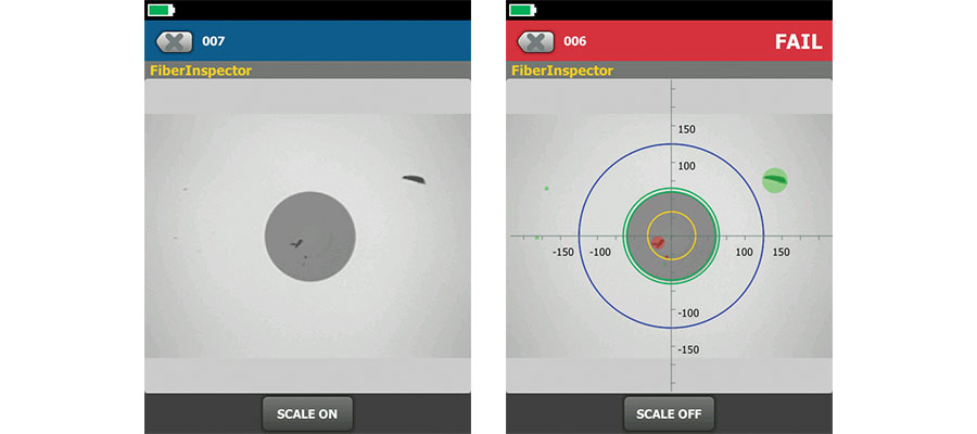
그림 4: Is the end face shown on the left clean or dirty? Automated certification demonstrates that it is dirty per IEC 61300-3-35 due to defects in the core (Zone A).
All end faces — even brand new and factory-terminated plugs and pigtails — should be inspected for cleanliness before mating. That includes both ends of fiber optic test cords, fiber jumpers, and pre-terminated trunk cables.
If you are using an adapter to mate two plugs, the end faces on both sides and the sleeve of the adapter should all be inspected and cleaned, if necessary, before inserting them into the adapter. Interchangeable adapters used with optical power meters also need to be inspected on a regular basis; often the adapter has a light shield with a pinhole that can accumulate debris. Always consult the documentation that came with the testing equipment you use, as some vendors require sending certain adapters back for factory cleaning.
When you are testing or troubleshooting any equipment, including the tester itself, all plugs and ports should be inspected and cleaned, if necessary, before mating. That includes test equipment ports, adapters, test cord end faces, and any ports into which you will connect the test cord.
Dust caps and mating can be a source of contamination. Therefore, every time you unplug or remove a dust cap or port from a fiber end face, even when it is brand new, it should be inspected and cleaned, if necessary, prior to being inserted. Ports should also always be inspected and cleaned, if necessary, before inserting a connector, even if one was just recently removed.
The Best Tools for Cleaning Fiber End Faces
Cleaning fiber end faces requires two materials: wipes and solvent.
Do not use canned air and dusters to clean fiber end faces. They just blow particles around to contaminate another location. They cannot effectively clean oils, residues, or small, charged dust particles — and they often expel a propellant that can become a whole new contaminant to remove.
Fabric and composite wipes made of lint-free material provide enough absorbency to remove contaminants from the fiber end face. In general, avoid cleaning against hard surfaces. If you are using a wipe or cassette type cleaner, typically one or two short strokes (approx. 1 cm) on the cleaning material is sufficient. Apply enough pressure for the wipe to conform to the end face geometry and ensure that the entire end face has been cleaned.
Using wipes alone is referred to as “dry cleaning,” which has been proven to be only partially effective in eliminating contaminants. Dry cleaning can also leave a static charge on the end face that can actually attract dust particles after cleaning.
A better way to clean a fiber end face is to use solvents in conjunction with wipes. Solvents add a chemical action that increases the cleaning ability of the wipe to lift particles and debris from the end face while eliminating the static charge issue with dry cleaning. Avoid using large amounts of solvent; the excess can leave behind a film of dissolved contaminants. To remove excess solvent, follow wet cleaning with dry cleaning by either moving to the dry area on the wipe or by following up with a new dry wipe. This is referred to as “wet-dry cleaning” and is the industry-recommended cleaning procedure. Be careful not to overdo the dry part and create a static discharge.
The solvent you use should be specially formulated for fiber end face cleaning. Isopropyl alcohol (IPA) was used for many years to clean fiber end faces, but it can leave behind a “halo” as it dries, which causes attenuation and can be difficult to remove. The specialized solvents preferred now, such as those in our Fiber Optic Cleaning Kits, have a lower surface tension that makes them far more effective at enveloping debris for removal and dissolving contaminants (see Figure 5). No solvent should remain on the end face after cleaning.

그림 5: Specialized solvents (left) are far more effective at cleaning end faces than isopropyl alcohol, which can leave behind hard-to-remove residue (right).
To clean fiber end faces inside ports or equipment, specially designed lint-free swabs or mechanical port cleaning devices — like our Quick Clean cleaners — work better than wipes.
- When using swabs for cleaning inside ports, apply just enough pressure to clean the end face as you rotate the swab several times in one direction.
- When using solvents for port cleaning, do not use excessive solvent to saturate the plug interface. The evaporation rate of a solvent is significant with port cleaning because it is harder to guarantee the removal of all solvent. Lingering solvent can become trapped during mating and cultivate harmful residue over time. This is another reason to use only solvents that are specially formulated for cleaning fiber — these solvents stay long enough to work but evaporate much faster than IPA.
- A good way to avoid using too much solvent it to apply a drop of solvent on a wipe and touch the swab to the wipe.
It is also important to remember that these tools are consumables: once you use a wipe or swab to clean an end face, discard it immediately. 더러운 와이프 또는 면봉을 재사용하면 오염이 아주 쉽게 퍼집니다.
While cleaning jumpers and test reference cord end faces is also important, these components are also consumables which will eventually fail. Sometimes even careful cleaning is not enough if these items have reached the end of their service life following the vendor’s specified number of insertions.
Don't Let Dirty End Faces Pose a Risk to Your Fiber Network: Inspect Every One
Network uptime, signal transmission performance, and equipment reliability are critical for data centers as well as for on-premises enterprise networks. Skimping on inspecting and cleaning fiber optic end faces can result in dire consequences.
Every fiber end face should be carefully inspected and certified according to the IEC 61300-3-35 standard prior to making a mated connection. If an end face fails inspection, be sure to test its optical performance to determine if it needs to be replaced. By making fiber inspection and certification a key part of your process, you can avoid the most common cause of fiber-related problems in today’s complex networks.
Fluke Networks Fiber Inspectors Automatically Certify Fiber End Faces to IEC Standards
The Fluke Networks FI-7000 FiberInspector™ Pro, FI2-7300 FiberInspector Pro MPO, and FI-3000 FiberInspector Ultra Camera use algorithmic processes to quickly inspect, grade, and certify fiber end faces based on IEC standard criteria. They provide automated PASS/FAIL results that remove human subjectivity and guesswork from fiber inspection.
Our FiberInspector testers are ideal for inspecting end faces inside ports or on patch cords. To clearly indicate which defects pass or fail the standard’s requirements, these inspectors offer pinch-and-zoom touchscreen interfaces that allow you to zoom in on individual fibers; defects that fail show red, and those that pass show green. The FiberInspector Ultra Camera also offers PortBright™ illumination for inspection in dark and crowded environments.

그림 6: Fluke Networks FiberInspector testers allow users to switch seamlessly from a summary view (left) to an end face image (center), then use the gesture-based interface to zoom in on each fiber (right) and pan across the entire connector. 개별 광케이블에 라벨이 붙어 있어 어느 것을 보고 있는지 알 수 있습니다. Red defects are failures; green defects are acceptable to the selected standard.
FiberInspector testers also integrate with the Versiv™ Cabling Certification System for fast, error-free project management, reporting, and storing images of fiber end faces directly in your Versiv test results. When used with a Versiv mainframe, FiberInspector solutions work with LinkWare™ software that lets you combine Tier 1, Tier 2, and inspection results into a single report for full documentation of every link in the system. The cloud-based version, LinkWare Live, makes it easy to track the progress of the job from your smartphone or PC and share results with customers.
Learn more about Fluke Networks Fiber Inspection solutions here.
Cable Certification with the Fluke Networks Versiv Family
The Versiv family accelerates every step of the inspection and certification process. Future-ready design supports fiber loss, OTDR testing, and hardware upgrades. The revolutionary ProjX™ management system and Taptive™ user interface ensure jobs are done right the first time. LinkWare 관리 소프트웨어를 사용하여 테스트 결과를 분석하고 전문적 테스트 보고서를 작성합니다.
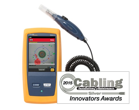 FiberInspector™ Pro
1-second automated PASS/FAIL certification of fiber connector end faces to the IEC 61300-3-35 standard.
 FI-3000/F12-7300 FiberInspector™ Ultra Camera
The easy, efficient, and complete inspection solution gives total end face visibility from full trunk to individual end face.
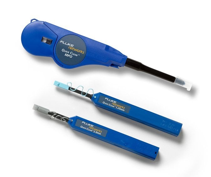 광선로 청소 키트
Precision end face cleaning for all fiber cable connector types, which eliminates the #1 cause of fiber link failure: 없습니다.
 CertiFiber® Pro Loss Test Set
Accelerates every step of the fiber certification process, with the fastest time to certify (two fibers / two wavelengths in under three seconds).
 OptiFiber® Pro OTDR
Enterprise fiber troubleshooting and certification for LAN, data center, PON, FTTx, and outside plant applications.
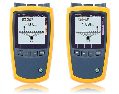 MultiFiber™ Pro MPO 테스터
The first fiber tester to support both single-mode and multimode MPO fiber certification.
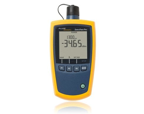 SimpliFiber® Pro Optical Power Meter
Easy-to-use fiber loss tester with single-port, simultaneous dual wavelength testing and other advanced time-saving features.
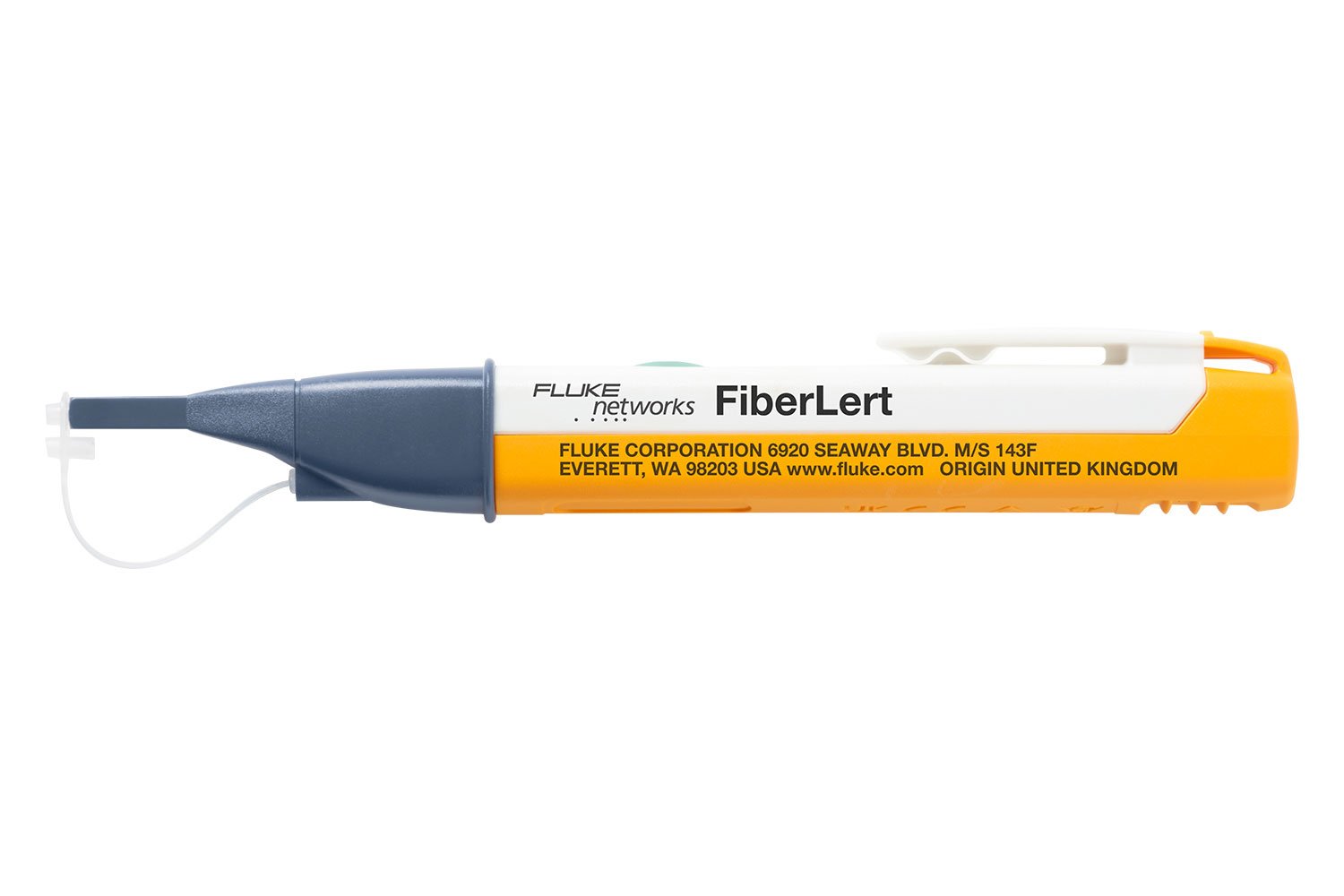 FiberLert™ 라이브 광케이블 탐지기
Detects active single mode and multimode optical signals for testing ports, cables, and polarity.
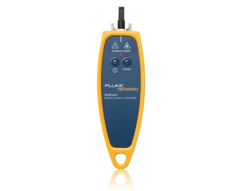 VisiFault™ Visual Fault Locator–Cable Continuity Tester
Locate fibers, find faults, verify continuity and polarity, and accelerate end-to-end fiber checks.
 LinkWare™ Live Results Management Service
A cloud-based service that lets Versiv users manage cabling certification jobs anytime, anywhere, with anyone, on any device.
 LinkWare PC 케이블 테스트 관리 소프트웨어
Manage all test results from multiple testers using one PC application that saves time and delivers professional reports in a common format.


