Insertion Loss
August 25, 2021 / General, 101 learning, Installation and testing
What is Insertion Loss?
Insertion loss is the amount of energy that a signal loses as it travels along a cable link. It is a natural phenomenon that occurs for any type of transmission—whether it's electricity or data. This reduction of signal, also called attenuation, is directly related to the length of a cable—the longer the cable, the greater the insertion loss. Insertion loss is also caused by any connection points along a cable link (i.e., connectors and splices).
Insertion Loss Formula
A key performance parameter for both copper and fiber applications, insertion loss is measured in decibels (dB). It is typically a positive number that is calculated by comparing the input power of the signal at the source to the output power at the far end. The lower the insertion loss, the better the performance. If insertion loss is too high, it can prevent the signal from properly being received and interpreted by active equipment at the far end of a link. Because insertion loss is directly related to distance and the number of connection points, industry standards call out insertion loss limits and specify the number of connections and distance limitations for specific applications.
Insertion Loss vs. Return Loss vs. Reflectance
Like insertion loss, return loss is another parameter that is important in both copper and fiber systems. Rather than measuring the amount of loss over a link, return loss measures the amount of power injected from the source compared to the amount reflected back toward the source. Like insertion loss, return loss is also a positive number. However, unlike insertion loss, the higher the number, the better the performance. Decreased reflections result in a higher return loss. In other words, if none of the signal was reflected, there would be an infinite return loss. A higher return loss also generally correlates to a lower insertion loss. It’s important to note that in optical fiber applications, the inverse of return loss is reflectance, which measures the amount of back reflection created by a reflective event (i.e., connector) compared to the amount of light injected. Also expressed in dB, reflectance is a negative number. Learn more in our article about the difference between return loss and reflectance.
Insertion Loss in Optical Fiber
Insertion loss in optical fiber cabling systems is much less than copper, which is why fiber supports much greater distances and long-haul backbone applications. For example, multimode fiber loses only about 3% (0.3 dB) of its original signal strength over a 100-meter distance while a Category 6A copper cable loses about 94% (12 dB) of its signal strength over the same distance. Still, there are limits on the amount of insertion loss that specific fiber applications can handle, and higher bandwidth applications have more stringent loss requirements. For example, the 10 Gb/s application 10GBASE-SR over 400 meters of multimode fiber allows a maximum channel insertion loss of 2.9 dB, while the 100 Gb/s application 100GBASE-SR4 allows a maximum of just 1.5 dB.
Fiber Insertion Loss Budgets
Based on the maximum insertion loss values published by industry standards for specific applications, loss budgets are determined early in the design phase to ensure that the cable plant does not exceed the maximum specification. Based on manufacturer specifications for the fiber and connectors, as well as the maximum specified loss of any splices or splitters, fiber insertion loss budgets are calculated by adding the insertion loss for the length of fiber and for each planned connection point in the channel. The active equipment also needs to be considered per the equipment manufacturer’s specifications based on any differences between transmitters and receivers, as well as some margin to account for loss of power over time that can occur due to transmitter age. Learn more about calculating and ensuring loss budgets.
How to Test Insertion Loss in Optical Fiber Systems
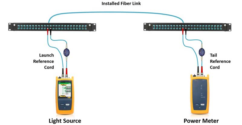
Because insertion loss is the primary performance parameter that impacts the ability of a fiber link to support a given application, it is required for fiber certification testing per industry standards. An Optical Loss Test Set like Fluke Networks’ CertiFiber® Pro provides the most accurate insertion loss measurement on a link by using a light source on one end and a power meter at the other to measure exactly how much light is coming out at the opposite end. Both TIA and ISO standards use the term “Tier 1” to describe testing with an OLTS.
Some projects will also specify extended “Tier 2” testing that requires an Optical Time Domain Reflectometer (OTDR) to characterize the loss of individual splices and connectors. An OTDR achieves this by transmitting light pulses into a fiber and measuring the amount of light reflected from each pulse. An OTDR is also typically required for calculating return loss of specific connectors and is therefore essential for applications like short-reach single-mode where maximum insertion loss is based on the number and return loss of connectors in a channel. It’s important to note, that the use of an OTDR in Tier 2 testing does not replace the OLTS because the total insertion loss measurement achieved with an OTDR is an inferred calculation that does not necessarily depict the total loss that will occur on a link once it is live. So even if a specification requires extended Tier 2 testing, Tier 1 insertion loss testing via an OLTS is still required. In these scenarios, it is also recommended that OTDR characterization be done before OLTS insertion loss testing since it is required for final proof of compliance. Read about using both an OLTS and an OTDR for a complete testing strategy.
Insertion Loss Testing Procedure for Optical Fiber
Insertion loss testing in today’s multimode fiber optic systems requires the use of encircled flux (EF) launch conditions to reduce measurement uncertainty. This method controls how the light is launched into a fiber under test to prevent an overfilled launch that can potentially cause a pessimistic result or an underfilled launch that can result in an optimistic result. Fluke Networks only provides EF-compliant testers and test reference cords for 850 nm and 1300 nm for all multimode fiber types. Learn more about EF compliance.
The default testing procedure for insertion loss testing is the 1-jumper method that includes the loss of the connections at both ends, which is ultimately how the cabling plant will be used. To accurately test the loss of the first and last connectors, they must be mated to a similar, known quality connector using Test Reference Cords (TRCs). TRCs are high quality test cords that are terminated with reference grade connectors and optical alignment of fiber cores that exhibit an extremely low loss of less than 0.2 dB for single-mode and less than 0.1 dB for multimode. Typical fiber jumpers used for normal day-to-day patching range between 0.3 dB and 0.5 dB and should not be used for testing.
To account for the loss of the TRC, an OLTS must be calibrated to 0 dB of loss by setting a reference—a concept similar to placing a bowl on a scale and then calibrating the scale to zero to achieve an accurate weight for whatever is in the bowl. Setting the reference is easy with Fluke Networks’ CertiFiber Pro’s Set Reference Wizard that takes users step by step through the process. Learn how to set a fiber tester reference using the Set Reference Wizard.
Insertion Loss Example
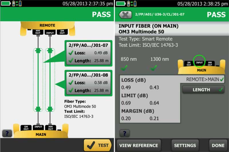
Testing insertion loss with a Fluke Networks’ CertiFiber Pro OLTS provides an easy pass/fail indication based on the type of fiber under test and the application test limits, indicating the overall loss of the link and the length. As shown in the insertion loss example below, the dotted line indicates what’s included in the measurement and the “Detail” window shows the margin and allowable limits for the fiber at both wavelengths.
Insertion loss testing results for each fiber link can also be uploaded and managed via LinkWare™ Live, a cloud-based service that allows for generating certification reports and sharing, tracking, and managing all project test results. In addition to the insertion loss results, a LinkWare insertion loss certification report includes information about the fiber being tested, the cable ID, connector type and test limits, date and time, and even calibration and software information about the tester.
Causes of Insertion Loss in Optical Fiber Systems
Exceeding the insertion loss for a given application can be a result of inferior quality components or poor field termination such as connector misalignment or dirty fiber end faces. In fact, end face contamination remains the primary cause of insertion loss. If the system has undergone moves, adds and changes without properly cleaning and inspecting the fiber end faces, what may have been clean at the time of installation may now be dirty and adding insertion loss to the channel. Other causes can include miscalculations when determining the insertion loss budget or the chance that something changed during installation, such as a connection being added or the link being longer than planned. Post installation issues can also be caused by the customer upgrading to a higher-speed application that has more stringent insertion loss requirements than what was used in the original insertion loss budget calculations. Learn more about causes of insertion loss.
As previously mentioned, good return loss performance is also a good indication of good insertion loss performance. While insertion loss is the primary performance parameter needed to ensure support for an application, there are some applications more susceptible to reflectance where the number and return loss values of connectors can impact allowed maximum insertion loss. This is the situation low-cost, low-power transceivers used in newer short-reach single-mode applications. Learn more about insertion loss requirements in short-reach single-mode.
Troubleshooting Insertion Loss in Optical Fiber
When insertion loss fails certification testing with an OLTS, the best way to pinpoint the problem is to use an OTDR that can measure the loss of specific events such as breaks, bends, splices and connectors. This can allow technicians to determine the cause and exact location of the loss event. An OTDR provides a graphical trace that characterizes each loss even along a fiber link.
While experienced OTDR users will recognize events for tester connectors, launch cords, connectors, mechanical splices, fusion splices, mis-matched fibers, and the end of the link, not everyone is a trace analysis expert. Thankfully, advanced OTDRs like Fluke Networks OptiFiber™ Pro include an easy-to-read graphical Event Map that analyzes loss events using advanced logic that automatically interprets the trace. Get more information about troubleshooting insertion loss.
Insertion Loss in Copper
Because insertion loss occurs for any type of transmission, it is also a performance parameter in copper cabling systems. Compared to fiber, copper cabling systems exhibit much more insertion loss. A key difference is also the fact that signal loss over copper changes with the frequency of the signal—copper links exhibit more loss for higher frequency signals. For example, the maximum allowed insertion loss for Category 5e specified to 100 MHz is around 22 dB, while Category 6 specified to 250 MHz is a little over 32 dB.
How to Test Insertion Loss in Copper Cabling Systems
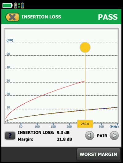
Because insertion loss changes with frequency, it is tested over the entire frequency range for a given application. For example, in a Category 5e channel, insertion loss is tested from 1 MHz to 100 MHz. For Category 6A, it is tested from 1 MHz to 250 MHz. Fluke Networks’ DSX CableAnalyzer series of testers automatically tests at each frequency based on the application being tested and plots results over the entire frequency as shown below. Get for more information on how to measure and test insertion loss in copper systems.
3 dB Rule
According to industry standards, copper insertion loss results less than 3 dB are ignored. This is referred to as the “3 dB rule” and is applicable to all copper cabling standard test limits. In very short lengths, the insertion loss may never reach 3 dB and the entire measurement will therefore be ignored. Learn more about the 3 dB rule.
4 dB Rule
In addition, near-end crosstalk measurements that occur at an insertion loss of less than 4 dB are also ignored. If the insertion loss never reaches 4 dB, the entire near-end crosstalk measurement is ignored, even when near-end crosstalk exceeds the limit. Learn more about the 4 dB rule.
Insertion Loss Deviation
Insertion loss deviation (ILD) caused by component impedance mismatch in a copper channel is a consideration at higher frequencies in high-speed, full duplex applications as it can create noise that degrades performance. In these applications, a ripple can occur in insertion loss results at high frequencies (typically above 75 MHz) on links exhibiting structural impedance variations. This ripple increases in magnitude as a function of frequency and the amount of structure in the cable. While not a field test parameter, manufacturers measure ILD as the worst case difference in magnitude between the expected insertion loss and the actual measured insertion loss. Read more about insertion loss deviation.
Causes of Insertion Loss in Copper Cabling Systems
In copper cabling, insertion loss is largely dependent upon the gauge of wire—23 AWG wires will have less insertion loss than the same length 24 AWG (thinner) wires. Wire gauges have therefore increased for higher frequency applications with Category 5e typically at 24 AWG and Category 6A at 22 or 23 AWG. That's also why some of the new popular thinner 28 AWG cables are limited to shorter distances to compensate for the increased loss. Also, stranded copper cabling exhibits 20-50% more insertion loss than solid copper conductors, which is why solid conductors are used for the longer permanent link portion of a copper channel and stranded conductors are limited to shorter patch cords. For copper cabling, attenuation can also be related to temperature.
Higher temperatures cause more attenuation in all cables, which is why standards specify maximum operating temperatures for copper cabling or require length de-rating for hotter operating environments. This is also a concern in copper cables carrying DC power via remote powering technologies like power over Ethernet (PoE) that can cause the temperature to further increase, especially in cables located in or near the middle of a cable bundle that can’t properly dissipate heat. Learn more about the impact of temperature on insertion loss and standards requirements.
In addition, the use of lubricant on cables to facilitate installation can cause an insertion loss failure—even when everything else passes. Lubricant is highly conductive, which causes electrons to disappear from the cable and not picked up by the tester. Over time, as lubricant cures and becomes less conductive, insertion loss will improve.
What Makes Good Insertion Loss Testing Equipment?
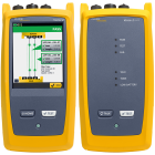
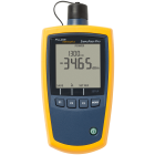
Whether you’re testing fiber or copper, the key to a good insertion loss tester is accuracy. For fiber certification testing, that means you need an Encircled Flux-compliant tester with the ability to test multimode and single-mode fiber links at multiple wavelengths and advanced automatic Pass/Fail analysis to industry standards or custom test limits. Additionally, the ability to set up a tester easily and accurately can go a long way in reducing time and preventing testing errors. Part of the Versiv™ cabling certification product family, Fluke Networks’ CertiFiber(TM) Pro is a highly accurate optical loss test set that includes all of these features to accelerate every step of the fiber certification process. CertiFiber Pro can also easily be updated with the latest firmware to support new applications, supports LinkWare™ Live cloud-based result management and is backed by a comprehensive protection plan with 24x7 technical support. For quick, simple insertion loss verification and troubleshooting, Fluke Networks’ SimpliFiber Pro optical power meter is an advanced time-saving, lower-cost tester that also tests insertion loss at multiple wavelengths and works with LinkWare Live.
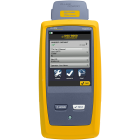
For copper certification testing, it’s important to select a tester with standards-based Level V accuracy that has undergone rigorous evaluation by an independent and technically qualified laboratory. The tester should have the ability to certify the performance of all categories of cable and current applications. It should show results for all parameters on all four pairs of a cable, including insertion loss. This is especially important since insertion loss being higher on only one or two pairs can be an indication of a bad connection. In addition, a tester with diagnostic capabilities can reduce the time required to fix cabling faults. Fluke Networks' DSX CableAnalyzer(TM) series of copper certification testers meet all of these requirements, and as part of the Versiv platform, it can also easily be updated with the latest firmware to support new applications, supports LinkWare™ Live cloud-based result management and is backed by Fluke Networks’ comprehensive protection plan.


